Transcription of Learning the Routing Table Structure - Del Mar College
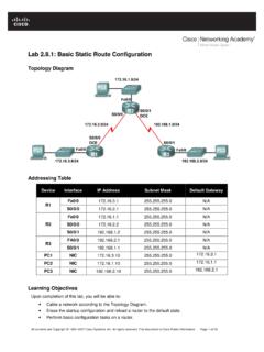
1 The Routing Table Part I Understanding the Routing Table Structure By Rick Graziani This document is the first of two parts dealing with the Routing Table . Part I discusses the Structure of the Routing Table , how routes are created. Part II discusses the Routing Table lookup process. The network we will be using is a simple three router network. RouterA and Router B share a common network. RouterB and RouterC are connected by the network. You will notice that RouterC also has a subnet which is disconnected, or discontiguous, from the network that RouterA and RouterB shares. This was done on purpose, and will be significant in Part II The Routing Table Lookup Process.
2 Router BRouter CRouter One last note before we begin. In order to keep this document simple and brief (and for those of you who know me, that is not easy for me to do!), I have left out some of the detail and exact terminology. For those of you who are interested in reading more about this subject and the inner-workings of the cisco IOS as it pertains to Routing , I highly recommend the book, cisco IP Routing , by Alex Zinin (ISBN 0-201-60473-6). However, this is not a book for beginners and does contain some pseudocode which can be skipped if you wish. 1 Part I Adding Routes to the Routing Table We will begin by assuming the following configurations have already been done to the three routers.
3 If you are using the document as a lab, configure the routers with these configurations. You will notice that we have not added any static routes or dynamic Routing protocols. The DCE cable is attached the serial interfaces of RouterA and RouterC. The command exec-timeout 0 0 is an optional command that keeps the router from exiting privileged mode when the idle timer expires. The other optional command is logging synchronous. This command eliminates debug and other output from becoming intermixed with the router prompt and input commands. RouterA hostname RouterA ! interface FastEthernet0 ip address !
4 Interface Serial0 ip address clockrate 64000 ! line con 0 exec-timeout 0 0 logging synchronous RouterB hostname RouterB ! line con 0 exec-timeout 0 0 logging synchronous RouterC hostname RouterC ! interface FastEthernet0 ip address ! interface Serial0 ip address clockrate 64000 ! line con 0 exec-timeout 0 0 logging synchronous 2 Creating an Ultimate Route Since we have not configured any interfaces for RouterB, the Routing Table for RouterB does not currently contain any routes (Figure 1). Figure 1 RouterB#show ip route Codes.
5 C - connected, S - static, I - IGRP, R - RIP, M - mobile, B - BGP D - EIGRP, EX - EIGRP external, O - OSPF, IA - OSPF inter area N1 - OSPF NSSA external type 1, N2 - OSPF NSSA external type 2 E1 - OSPF external type 1, E2 - OSPF external type 2, E - EGP i - IS-IS, L1 - IS-IS level-1, L2 - IS-IS level-2, ia - IS-IS inter area * - candidate default, U - per-user static route, o - ODR P - periodic downloaded static route Gateway of last resort is not set RouterB# Before we configure the interfaces, we will use the debug ip Routing command (Figure 2), which allows us to view the Routing Table process adding, deleting, and modifying entries.
6 As usual, don t forget to use the undebug ip Routing or undebug all command to turn off debugging. Figure 2 RouterB#debug ip Routing Now, let s begin by configuring RouterB s serial 1 interface (Figure 3). The output from the debug ip Routing command is highlighted in Figure 3. Other IOS output has been omitted. Figure 3 RouterB(config)#interface s 1 RouterB(config-if)#ip add RouterB(config-if)#no shutdown 00:59:48: %LINK-3-UPDOWN: Interface Serial1, changed state to up 00:59:48: %LINEPROTO-5-UPDOWN: Line protocol on Interface Serial1, changed state to up 00:59:48: RT: add via , connected metric [0/0] 00:59:48: RT: interface Serial1 added to Routing Table RouterB(config-if)#end RouterB#undebug all All possible debugging has been turned off RouterB# 3 When an interface is configured with the line protocol and status in the up state, the network, or subnet, that the interface belongs to is added to the Routing Table with an administrative distance of 0.
7 (Figure 4) Figure 4 RouterB#show ip route Codes: C - connected, S - static, I - IGRP, R - RIP, M - mobile, B - BGP <text omitted> Gateway of last resort is not set C is directly connected, Serial1 RouterB# Lets take a look at this entry in more detail. Some of this may seem obvious, but there are some very important items that need to be addressed. First of all, this type of Routing Table entry is known as an ultimate network route. To be an ultimate network route, the route must have the following characteristics: The network route is a classful (major) network or a supernet/default route. In our case is a major, Class C network.
8 The route can be resolved using an exit interface. Directly connected networks use the interface on which the interface was configured as the exit interface. We will see later that this may not necessarily be the case for static or dynamically learned routes. In our directly connected network example, the exit interface is Serial1. Besides the code for how the route was learned (C for ) and the classful or supernet network, ultimate network routes in the Routing Table will also contain: The subnet mask, which is either the classful mask or a supernet mask. We will discuss supernet masks later in the Part II. In our example, /24 is shown as the subnet part of the ultimate route.
9 The exit interface, which is once again, Serial1. Notes: There is another type of ultimate route, the child/ultimate route which is discussed in the next section, Creating a Parent/Child Route. In Part II The Routing Table Lookup Process, we will examine how the subnet mask is used to determine the longest-bit match when determining the best route. It is the exit interface that ultimately (thus ultimate route ) determines which interface the Routing Table will use to forward the packets. An exit interface must exist for the packet to be routed. Later we will see where the Routing Table must do recursive or multiple lookups in order to find an ultimate route in the Routing Table with an exit interface.
10 To summarize, an ultimate network route is created in the Routing Table when the network is a classful (major) network and the route contains an exit interface. An ultimate network route can also be a supernet or default route which will be discussed later in Part II. This is regardless of how the route entered the Routing Table , either directly connected, statically configured or dynamically learned. Other situations will be discussed in the next section, Creating a Parent/Child Route. 4 Creating a Parent/Child Route Now lets see what happens when a route is created that is a subnet of a major or classful network. Figure 5 shows the configuration of RouterB s fastethernet interface with an IP address of and a subnet mask of (/24) and the output from the debug ip Routing command.