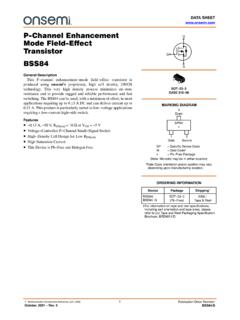
Transcription of Lecture 8 - MIT
1 Spring 2007 Lecture 81 Lecture 8 MOSFET(I)MOSFET I-V : cross-section, layout, characteristicsReading Assignment:Howe and Sodini, Chapter 4, Sections :Quiz#1, March 14, 7:30-9:30PM, Walker Memorial; covers Lectures #1-9; open book; must have Spring 2007 Lecture 821. MOSFET: layout, cross-section, symbols Inversion layer under gate(depending on gate voltage) Heavily doped regions reach underneath gate inversion layer to electrically connect sourceand drain 4-terminal device: bodyvoltage importantKey elements: deposited oxidefieldoxiden+ drain diffusiondraininterconnect p+[ p-type ]bulkinterconnectLdiffgate contact(a) Adraincontactsbulkcontactn+ polysilicon gate active area (thinoxide area)polysilicon gatecontactmetalinterconnectn+ source diffusionedge ofactive area sourceinterconnect(b)Ln+ polysilicon gate gate oxidegateinterconnectsource Spring 2007 Lecture 83 Circuit symbolsTwo complementary devices.
2 N-channel device (n-MOSFET) on p-substrate uses electron inversion layer p-channel device (p-MOSFET) on n-Si substrate uses hole inversion layern+n+pBulk orBodyDrainSourceGate(a) n-channel MOSFET D G IDpBp+p+nBulk orBodyDrainGate(b) p-channel MOSFETS ource+_VSGDS G++_VGSIDnIDnBVSD > 0 VDS > 0 +_VBS+_VSBDGBSSSBDG Spring 2007 Lecture 842. Qualitative Operation Drain Current (ID): proportional to inversion charge and the velocity that the charge travels from source to drain Velocity: proportional to electric field from drain to source Gate-Source Voltage (VGS): controls amount of inversion charge that carries the current Drain-Source Voltage (VDS).
3 Controls the electric field that drifts the inversion charge from the source to drainWant to understand the relationship between the drain currentin the MOSFET as a function of gate-to-source voltageand drain-to-source consider source tied up to body (substrate or back)depletion regioninversion layern+pn+ Spring 2007 Lecture 85 Three Regimes of Operation:Cut-off Regime MOSFET: VGS< VT, with VDS 0 Inversion Charge = 0 VDSdrops across drain depletion region ID= 0depletion regionn+n+DGSpno inversion layeranywhereVDS 0 VGS< Spring 2007 Lecture 86 Three Regimes of Operation:Linear or Triode RegimeElectrons drift from source to drain electrical current!
4 VGS |QN,| ID VDS Ey, ID depletion regionn+n+DGSpinversion layereverywhereVDS 0 VGS>VTVGD>VTVGD= VGS-VDSVDS<< Spring 2007 Lecture 87 Three Regimes of Operation:Saturation Regime VDS> VGS-VT VGS> VT, VGD< VT---> VDS> VGS-VTIDis independent of VDS: ID=IdsatElectric field in channel cannot increase with VDSdepletion regionn+n+DGSpinversion layer"pinched-off" at drain sideVGD<VTVGS> Spring 2007 Lecture 883. I-V Characteristics (Assume VSB=0)Geometry of problem:General expression of channel currentCurrent can only flow in the y-direction:Total channel current:Iy=W QN(y) vy(y)Drain current is equal to minus channel current:ID= W QN(y) vy(y)All voltages are referred to the Spring 2007 Lecture 89I-V Characteristics (Contd.)
5 Re-write equation in terms of voltage at location y, V(y): If electric field is not too high: For Qn(y), use charge-control relation at location y:vy(y)= n Ey(y)= n dVdyAll together the drain current is given by:ID=W nCoxVGS V(y) VT[] dV(y)dySimple linear first order differential equation with one un-known, the channel voltage V(y).ID= W QN(y) vy(y)QN(y)= CoxVGS V(y) VT[]for VGS V(y) VT.. Note that we assumed that VTis independent of y. See discussion on body effectin Section of Spring 2007 Lecture 810I-V Characteristics ( )Solve by separating variables:Integrate along the channel in the linear regime subject the boundary conditions :-Source: y=0, V(0)=0-Drain: y=L, V(L)=VDS(linear regime)Then:ID=WL nCoxVGS VDS2 VT VDSR esulting in:IDdy0L =W nCoxVGS V(y) VT[] dV0 VDS IDy[]0L=IDL=W nCoxVGS V2 VT V 0 VDSIDdy=W nCoxVGS V(y) VT[] Spring 2007 Lecture 811I-V Characteristics ( )Key dependencies: VDS ID (higher lateral electric field ) VGS ID (higher electron concentration)This is the linearortrioderegime.
6 It is linear if VDS<<VGS-VTID=WL nCoxVGS VDS2 VT VDSfor VDS<VGS Spring 2007 Lecture 812I-V Characteristics ( )Two important only valid if VGS V(y) VTat every y. Worst point is y=L, where V(y) = VDS, hence, equation is valid ifVDS VGS Spring 2007 Lecture 813I-V Characteristics ( )Two important VDSapproaches VGS VT, the rate of increase of :As y increases down the channel, V(y) , |QN(y)| , and Ey(y) (fewer carriers moving faster) inversion layer thins down from source to drain IDgrows more Spring 2007 Lecture 814I-V Characteristics ( )Drain Current SaturationAs VDSapproachesincrease in Eycompensated by decrease in |QN| IDsaturates when |QN| equals 0 at drain of drain saturation current.
7 ThenWill talk more about saturation regimenext VTIDsat=IDlin(VDS=VDSsat=VGS VT)IDsat=12WL nCoxVGS VT[]2 IDsat=WL nCoxVGS VDS2 VT VDS VDS=VGS Spring 2007 Lecture 815I-V Characteristics ( )Output CharacteristicsTransfer Spring 2007 Lecture 816 Output Spring 2007 Lecture 817 Summary of Key ConceptsIDsat=W2L nCoxVGS VT()2 MOSFET Output CharacteristicsI-V Characteristics in Saturation RegimeVDS VGS-VTI-V Characteristics in Linear RegimeVDS< VGS-VTID=WL nCoxVGS VDS2 VT VDSI-V Characteristics in Cutoff RegimeVGS< VT ID= 0