Transcription of Lecture 9 HYDRAULIC PUMPS [CONTINUED] 1.11 Pump ...
1 Lecture 9. HYDRAULIC PUMPS [ continued ]. Pump Performance Curve Pump performance characteristics are first analyzed independently of the rest of HYDRAULIC system and then as a part of the system. Both sets of data are valuable to the designer. Analyzing the pump by itself gives an indication of its capabilities and performance based on the speed of rotation, internal geometry, cost factors, etc., whereas analyzing pump performance in system essentially determines pump system compatibility. In the first case, the system designer may observe performance curves to see if a specific pump has the pressure and volume flow rate to operate a given set of actuators.
2 In a second instance, the system designer may be computing the noise, vibration, cavitation and flow characteristics of a specific pump before or after installation to determine if the pump and existing system are compatible. Where the two are necessarily complimentary, in practice much of hands-on work is completed independently. Pump performance characteristics are interpreted from data in tabular form and then graphed. Figure shows a graphical representation of a typical positive displacement pump.
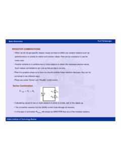
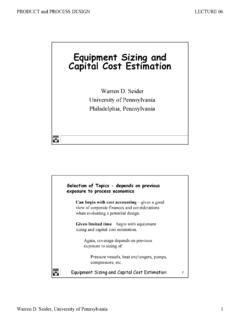
3 Figure (a) represents the relationship between input power and pump output flow of a variable displacement piston pump as a function of pump the linear relationship between the discharge flow and pump speed. Figure (b) gives curves of overall and volumetric efficiencies as a function of speed. Performance curves of radial piston pump are given in (c). Discharge flow of these PUMPS is nearly constant over a broad pressure flow can be varied infinitely between the point of inflection on the constant discharge portion of the curve and zero flow.
4 Flow Power (a). (b). (c). Figure performance curves Noise Pump noise is an important parameter used to determine the performance. Any increase in noise indicates increased wear and eventually pump failure. PUMPS are good generators but poor radiators of noise. Noise is not just the sound coming directly from the pump, but also from the vibration and fluid pulsation produced by the pump. PUMPS are small in size and hence, they are poor radiators of noise. Reservoirs, electric motors and piping being largerin size are better radiators.
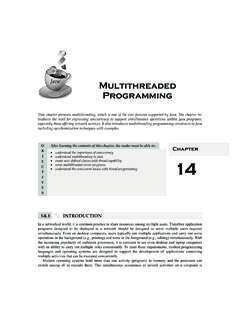
5 Hence,a pump-induced vibration can cause audible noise greater than that coming from the pump. Fixed displacement PUMPS are less noisy than variable displacement PUMPS because of their rigid construction. Figure Pumpnoise characteristics As can be seen from , the pump speed has a strong effect on noise compared to displacement and pressure. To reduce the noise levels, electric motors are used and the most advantageous combination of size and pressure is selected to produce the needed power. Cavitation During the working of a positive displacement pump, vacuum is created at the inlet of the pump.
6 This allows atmospheric pressure to push the fluid in. In some situations, the vacuum may become excessive, and a phenomenon known as cavitation occurs. When the pressure of the liquid reaches a low enough level, it vaporizes or boils. Cavitation is the formation of oil vapor bubbles due to a very low pressure (high vacuum) on the inside of the pump. The low pressure also causes air, which is dissolved in the oil to come out of the solution and form bubbles. These air and oil vapor bubbles collapse when they reach the outlet side of the pump, which is under a high pressure.
7 The collapsing of these vapor bubbles causes extremely high localized pressure and fluid velocity. These pressures are so high that they cause pitting of metal and consequently decrease the life and efficiency of the pump. Factors Causing Cavitation Cavitation is caused by the following factors: 1. Undersized plumbing. 2. Clogged lines or suction filters. 3. High fluid viscosity. 4. Too much elevation head between the reservoir and the pump inlet. Rules to Eliminate (Control) Cavitation Following are the rules to control cavitation: 1.
8 Keep suction line velocities below m/s. 2. Keep the pump inlet lines as short as possible. 3. Minimize the number of fittings in the inlet line. 4. Mount the pump as close as possible to the reservoir. 5. Use low-pressure drop inlet filters. 6. Use proper oil as recommended by the pump manufacturer. Example Calculate the pipe bores required for the suction and pressure lines of a pump delivering 40. L/min using a maximum flow velocity in the suction line of m/s and a maximum flow velocity in the pressure line of m/s.
9 Solution:Consider the suction line Flow = Average velocity Flow area Flow through pipe Area of pipe =. Velocity of flow Now Flow = 40 LPM = 40/60 LPS = 40/60 10 3 m3/s 40 10 3. Area of pipe = = 10 3 m2. 60 Let the bore of the pipe be of diameter D. Then 3 D 2. Area of pipe 10 m 2. 4. D = m Minimum bore suction pipe = mm. Note: in all calculations great care must be taken to ensure that units are correct. Alternatively, if a flow velocity of 1m/s is used then suction pipe bore can be of diameter 29. mm.
10 The required diameter of the pressure line can be calculated in a similar manner taking the flow velocity as m/s. Here the minimum bore of pressure pipe is equal to mm. It is unlikely that a pipe having the exact bore is available, in which case select a standard pipe having a larger bore. Alternatively, a smaller bore pipe may be chosen but it will be necessary to recheck the calculation to ensure that the flow velocity falls within the recommended range. That is, a standard pipe with an outside diameter of 20 mm and a wall thickness of mm is available.