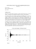
Transcription of Low-Frequency RFID in a Nutshell - TI.com
1 ApplicationReportSWRA284 September2011 Low-FrequencyRFIDina ,howtochoosetherightcomponents,andshowsb estpracticesfora guidelinefordesigninga RFIDS tickAntennaNeara (4ms/div)..33 ProgramPageCommandWithCorrectBCCandRespo nse(10ms/div)..44 ProgramPageWithIncorrectBCCandNoResponse (10ms/div)..45 PPMT imingfora September2011 Low-FrequencyRFIDin a NutshellSubmitDocumentationFeedbackCopyr ight 2011,TexasInstrumentsIncorporatedBase Station AntennaTransponder (LF)RFcommunicationtotherightpassivecomp onentsandfinallytoa (poweredbythemagneticfieldofa RFID reader)is chargephasein whicha capacitoris charged(TIhalfduplex(HDX)principle).
2 Read-onlydevicesthensendtheirinformation (typically96bits).Read/writedevicesneedt oreceivea (forexample,forpassiveentryorpassivestar tdevices)usethedownlinkchanneltoreceivea commandviaLFandwakea microcontrollerif therightwakepatternis (downlinkanduplink)thatis showshowtopositiona RFIDS tickAntennaNeara FromtheRFIDBaseStationtotheRFIDT ransponderAnRFID communicationis ,whichis sentbythebasestation, typicalcommunicationconsistsofa chargephaseof25msto50ms,whichis readanda programcommandareshownin Figure2 andFigure3.
3 Detectsa toFigure4 showa completecommunicationexchangebetweena V/divRFvoltageatthetransponderantenna2 VCLBlue2 V/divVoltageattheVCLchargecapacitor3 EOBM agenta1 V/divEndofburstdetectoroutputoftranspond er2 Low-FrequencyRFIDin a NutshellSWRA284 September2011 SubmitDocumentationFeedbackCopyright 2011,TexasInstrumentsIncorporatedCharge VCL CapacitorRead PageCommandResponseVCL Limit = 6 thevoltagethatis usedtochargetheVCLcapacitor(typically220 nF);VCLis theoperatingvoltageforthetransponderandi s limitedtoapproximately6 , a functionofdistance,antennasize,inductanc e,Q factor, ,datais transmittedusingOn/OffKeying(seeTable2 fortimings).
4 ThetimebetweentworisingedgesofEOBis longerthantbitH(seeTable2) a highbitis detected;otherwise,a lowbitis programpagecommand,a 2-byteBCCis ,a secondpowerburst(PowerBurst2,seeFigure3) is thereceivedBCC(neededforprogramandlockco mmands)is wrongorif theVCLleveldoesnotreachtheVCLcheckerlimi t,thetransponderperformsa dischargewithoutresponding(seeFigure4 fora programcommandwitha wrongBCC). (4ms/div)3 SWRA284 September2011 Low-FrequencyRFIDin a NutshellSubmitDocumentationFeedbackCopyr ight 2011,TexasInstrumentsIncorporatedCharge VCL CapacitorProgram Page Command +5 byte Data + Right BCCP ower Burst 2 ResponseCharge VCL CapacitorProgram Page Command +Power Burst 2 NoResponse5 Byte Data + Wrong (10ms/div) (10ms/div) a NutshellSWRA284 September2011 SubmitDocumentationFeedbackCopyright 2011, (PPM).
5 Figure5 showsthePPMtimingfora readpagecommand;Figure6 showsthetimingfora sInitialofftimetoff170 sStandardofftimetonH350 sTransmitterontimefora highbittbitH520 sPeriodfora highbittonL230 sTransmiterontimefora lowbittbitL400 sPeriodfora lowbittprg15msProgramtimenecessaryforpro grammingtheEEPROMtHdet510 sHighbitperiodmustbe210 s (minimum)to1730 s (maximum) ReadCommand5 SWRA284 September2011 Low-FrequencyRFIDin a NutshellSubmitDocumentationFeedbackCopyr ight 2011,TexasInstrumentsIncorporatedPREBITS STARTDISCHARGE16 Bits8 Bits48 Bits96 BCC8 Bits16 FromtheRFIDT ranspondertotheRFIDBaseStationAfterrecep tionofa validcommand,thetransponderprocessesthed ataandsendsa always96bitslongandhasthestructureshowni n Figure7; a detaileddescriptionofthefieldsis shownin TransponderLFCommandOnehighbitis representedby16sinusoscillationswitha ( s).
6 Onelowbitis representedby16sinusoscillationswitha ( s). TransponderResponseFIELDLENGTHNODEPREBIT S16bitsAlways16lowbits- 0x0000 START8 bitsDependsontypeoftransponder- TMS37157: 0x7 EDATA48bitsDependsontheperformedcommandR /WADDRESS8 bitsDependsontheperformedcommandFRAMEBCC 16bitsCalculatedfromSTART,DATA,andR/WADD RESS6 Low-FrequencyRFIDin a NutshellSWRA284 September2011 SubmitDocumentationFeedbackCopyright 2011,TexasInstrumentsIncorporatedTEST I/FTMS37157 PaLFINPORPUSHVBATIVBATCRCLRF1 LRGNDTENTCLKTDATVCLEOBBUSYVCLSPI_SIMOSPI _SOMISPI_ always96bitslong,resultingin a , thetransponderreceivesaninvalidcommand,i t showsonlythe16pre-bitsfollowedbydischarg ingtheVCLcapacitor(seeFigure4).
7 3 HowtoChoosetheRightPassiveComponentsA TexasInstrumentsRFIDlow-frequencytranspo ndersystemneedsonlya shownin M halfduplex(HDX)RFID systemrequiresa chargecapacitortostoreenergyforphasesdur ingwhichnomagneticfieldfromtheRFID basestationis 220-nFsurfacemountcapacitor,X7 Rtype,witha RFID circuitis ,a resonancecapacitorwitha lowvariationin capacityanda highqualityfactoris 470-pF 2%surface-mountcapacitor,NPO(CGO)type,wi tha (CGO)typecapacitorshavea highenoughqualityfactortoensurea a September2011 Low-FrequencyRFIDin a NutshellSubmitDocumentationFeedbackCopyr ight 2011, CapacitorTomeasurethequalityfactorandthe capacitanceofa capacitor,animpedanceanalyzeris showsthemeasurementperformedwitha (thenominalfrequencyofLFRFID).
8 Beawarethatthequalitymeasurementis NPOtyperesonancecapacitoris ,oneofthemostimportingfactorsfortheovera llqualityfactoroftheresonancecircuitis ,TexasInstrumentsrecommendsusinga (requiredforproperoperationoftheTMS37157 ) ,animpedanceanalyzeris (thenominalfrequencyofLFRFID).8 Low-FrequencyRFIDin a NutshellSWRA284 September2011 SubmitDocumentationFeedbackCopyright 2011,TexasInstrumentsIncorporatedf =res1 2 CLresantenna ResonanceCircuitTheresonancefrequencyofa resonancecircuitcanbecalculatedwithEquat ion1.
9 (1)Where: fres Resonancefrequencyoftheresonancecircuit Cres Resonancecapacitor Lantenna InductivityoftheantennaTheresonancefrequ encyofthecomponentsfromFigure9 andFigure10is (Cint, seeFigure11) ofapproximately30pF,whichmustbeaddedtoCr es. Inaddition, September2011 Low-FrequencyRFIDin a NutshellSubmitDocumentationFeedbackCopyr ight 2011,TexasInstrumentsIncorporatedCresCLR F1 LantennaVCLRLTrim Capacitor ArrayCintTMS37157 LF InterfacedBresBfQ3= ,a spectrumanalyzeris ,choosea , , isrecommendedtoplacetheRFcircuitawayfrom thesendcoilinitially(20cmormore),andthen closethedistanceuntila superelevationatthespectrumanalyzercanbe seen(seeFigure11).
10 Thedifferencebetweenthetwofrequencieswhe rethepoweris half(3dBlower)asin (2)Where: Q Qualityfactoroftheresonancecircuit fres Resonancefrequencyoftheresonancecircuit B3dB 3-dBbandwidth10 Low-FrequencyRFIDin a NutshellSWRA284 September2011 SubmitDocumentationFeedbackCopyright 2011, Figure12is calculatedwithEquation3.(3) determinedbydifferentfactors: Antennashouldhavea highQ (52to60) ResonancecapacitormustbeNPO(CGO)type InthePCBdesign,nometallayershouldbeunder neathoraroundtheantenna Nosignalroutingundertheantenna KeepPCBtracestotheantennashort,straight, andthin Keepantennapadsassmallaspossible Qualityfactorandresonancefrequencychange withtemperatureAnRFID systemis describedbythepartsoftheresonancecircuit (antenna,capacitor)