Transcription of Maintenance and Service Instruction
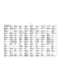
1 Screw pumpsACG/UCG 7 Maintenance and ServiceInstructionThis Instruction is valid for all ACG/UCG pump models shown on page 2 ContentsPageList of components2 Exploded view/Ordering code3 Service intervals4 Shaft seal/ Service for ball bearing4 Lubricating intervals/Useful tools5 Inspection of rotors5 Sectional view6 Dismantling7 Reassembly9 Pressure relief valve11 ACG1 ' IMO ABACG7 GBQtyComponents included in Spare parts sets:PosNo DenominationG011G012G050 G053G054 G057G070 Note1010 Power rotor (x)1020 Power rotor piston1xxx5113 Shaft key1xxx120 Distance sleeve1122 Ball bearing1xx124 Retaining ring1xxx124 ASupport ring1xxx201 Idler rotor (x)202 Idler rotor washer1359 ASupport ring1xxx401 Pump body1424 Sleeve14424 AWasher14429 Spindle14437O-ring14440 Return valve1451 Screw4/6453 Screw4462 Plug21462 ASealing washer2xxx1473 Grease nipple1473 AGrease nipple cover1480 Valve housing125010 Front cover1502 Tension pin16502 APlug16506 Gasket1xxx509 Shaft seal1xxx514 Retaining ring1xxx537 Plug2537 ASealing washer2xxx551 Rear cover13556 Gasket1xxx601 Valve cover1x2,7602 Sealing washer1xxxx2605O-ring1xxxx2608 Valve spindle1x2,7608 ARetaining ring1xxxx2612 Set screw1x2,7614 Valve piston1x2,7615 Valve spring1x2 Before commencing any work, read this Instruction carefully!
2 Failure to complywith these instructions may cause damage and personal injury!Valid for all pumps in sizes: ACG/UCG 045/052/060/070; Rotor diameter and generation: K7/N7 With version codes:Also valid for pump options: A101, A327, A385 Example of pump designationsstd: ACG 045N7 NVBP; option ACG 070N7 NVBP A101 List of componentsFor more information about the pumps identification code, technical data and performance we refer to theACG/UCG Product description. Fore more information about the pumps installation, Start-up and troubleshooting we refer to the IMO Installation and Start-up Instruction for low pressure :G011: Rotor setCCW-rotation optionG012: Rotor setCW-rotation (std)G050: Shaft sealG053: Minor kit(G050 + G057) + 122G054: Major kit consistingof: G053+G012 (G011)G057: Joint kitG070: Valve elementACG Pump with DINflangesUCG Pump with ANSI flangesA101: CCWA327: With TuningA385: CCW and TuningName plate of the pumpIMO ABACG2 ' IMO ABNTVBFEPG!
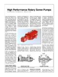
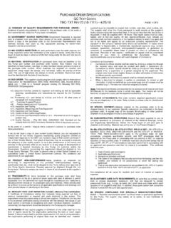
3 Notes:1) Excluded in xxxG2) Excluded in xxxE3) Valid for xxxE4) Valid for pump optionA3275) Included in item 1020or 10106) Included in item 50107) Only sold as GBACG/UCG xxBE/BP/BGFig. 1 Exploded viewVersion xVxxVersion xTxxxxxECCW rotation (non-standard)xxxPxxxGCW rotationOrdering codeRecommendation:For Maintenance thefollowing spare partsets are recommen-ded:Set:To be used:G057 Joint kitFor dismantling ofthe pumpG053 Minor kitFor serviceG054 Major kitFor repair afterdamage or parts sets Part numbers, sizesNo045052060070 Rotor set CW-rotation (std):G012 Normal lead - pump version N7178913 179507 179515 179523 "Low lead- pump version K7187542 187559 187567 187575 Rotor set CCW-rotation (non-std):G011 Normal lead - version N7186478 186486 186494 186502 Low lead- version K7189641 189642 189643 189644G050 Complete shaft seal - version code xVxx 190335 190336 190338 190340 - version code xTxx174094 174102 174110 174128G053 Minor kit- version code xVxx 191241 191243 191245 191247 - version code xTxx191242 191244 191246 191248G054 Major kit=G012(G011)+G053----G057 Joint kit191237 191238 191239 191240G070 Valve element - version code xxxP/G191250 191250 191251 191251122 BallbearingxxxxACG3 ' IMO AB 473537537A506401556480551453462462A46253 7537A473A1010201608A60160260560861261561 44534801020202113113509359359A514202124A 1241221204515010453462462A462 Details in pump option A327 See the sectional view p.
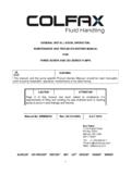
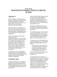
4 6 Fig. 2 Version xTxxVersion xVxxOrdering example:For IMO-pump ACG 045N7 NVBP, serial number 456789 Shaft sealpos G050 p/n 190335 Ballbearingpos 122 GBService intervalsThe intervals for inspection and replacement of wearparts vary greatly with the properties of the pumpedliquid and can only be determined by internal parts of the ACG-pump are lubricatedby the pumped liquid. Pumping liquid whichcontains abrasive materials, or liquid that is corro-sive, will significantly reduce Service lifeand call for shorter Service in the pump may be indicated by: Vibration Noise Loss of capacity Reduction in flow/pressure LeakageIn installations where unplanned shut downs mustbe avoided, it is advisable to have a complete pumpavailable for replacement, should any malfunctionoccur.
5 Furthermore we recommend planned inspec-tion and overhaul at regular intervals, not exceeding3 is recommended always to have the spares in-cluded in minor spare part kit for ball bearingThe ACG-pump is fitted with an external greaselubricated ball delivered from IMO AB, the ball bearings inpump version xVxx are filled with grease of type version xTxx, type C is the ball bearing is removed, it is recom-mended to exchange it for a new the new ball bearing properly greased andregrease it after one hour of running, while thepump is of shaft sealAs the seal faces of a mechanical shaft seal arelubricated by the fluid a certain leakage will alwaysbe present. Ten drops per hour can be considered external visual inspection of the pump is advis-able at least every two days to assure that the shaftseal is not leaking too leaking shaft seals should be changedwithout delay, as the leakage normally will growworse and cause additional the instructions in the dismantling/reassem-bly working with a shaft seal, cleanliness is ofutmost importance.
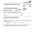
6 Avoid touching the seal faces. Ifnecessary, the seal faces should be cleaned immedi-ately prior to assembly, using a dustfree cloth andclean use grease on the seal seal - assembly drawingShaft seal G050 (pos 509)Version code xVxxVersion code xTxxS2 S1S5S2 S1 S4 S6 S9 S7 S5S1 SeatS2 O-ringS4 Seal ringS5 Seal ring carrierS6 O-ringS7 SpringS9 Stop washerS1 SeatS2 O-ringS5 Bellows unitFig. 3 ATTENTIONBe careful to mountthese parts in rightorder and in the pumps operating temperature exceeds60 C let the pump cool off before anyservice, Maintenance or dismantling work iscommenced to avoid burn work carried out on the pump has to beperformed in such a manner that risks forpersonal injury are observed!Use an appropriate type of grease, as per table and agrease gun suitable for grease nipple (pos 473)according to DIN 71 412 (ISO 6392).
7 On vertical mounted units the greasing intervals arereduced to in dusty or dirty premises or in a corrosiveenvironment it should be lubricated at more fre-quent using others than these recommended greasescheck if it is possible to mix them with each other,otherwise clean before using a new and disconnecting of electriccables must be done only by personnelauthorized to do such IMO AB!!! GBUseful toolsACG7 IMO ABSlide calliperPullerAllenkeysMounting sleeve dimensionsPump sizeD d LPart NoACG/UCG 045 052 060 070 can GreaseMoun-tingsleeve2 pcs ofscrewdriverPlasticmalletPair ofpliersFig. 4 Lubricating intervals in working hours TempPump sizes 045 and 052 Pump sizes 060 and 070max GreaseSpeed, r/minSpeed, r/min Ctype3500* 290017501450 11509503500* 29001750 1450115095070A 8500 10000 10000 10000 10000 1000075008500 10000 10000 10000 1000090A33503950535059506350750029503350 4750515059506750110B26503150425047005000 5950235026503750410047005350130B10501250 1650185020002350900105015001600185021001 55C6507501050115012501500600650950100011 501300*) at rotation speed > 3 500 r/min special instructions are given by IMO greases (the availability of the greases can differ locally):Type A.
8 BP Energrease LS 3, Esso Beacon 2, Mobilgrease HP 222, Shell Alvania G3, Texaco Multifak EP2, SKF LGMT2,Q8 REMBRANDT EP2, CASTROL APS2, ELF ROLEXA 3, TOTAL MULTIS TIR EP3, FINA MARSON B:BP Energrease LC2, CHEVRON SRI GREASE 2, Esso Unirex N3, Mobilith SHC220, SHELL RETINAX LX,SHELL Albida LX, VAL-PLEX EP GREASE, Texaco Hytex EP2, SKF LGHQ 3, Q8 RUBENS, CASTROL LMX,INDUSTRIAL GREASE HEAVY, TOTAL MULTIS THT2, FINA PLUTON C:Mobilith SHC 460 Before any Maintenance work, ensurethat the driver is deenergized and thepump hydraulically isolated.!!!Oil leakage may make the floor slipperyand cause personal handling liquids that may harmskin use gloves and/or protective clothing.!!Pump size045052060070 Grease amount (g)4679dDGREASELI nspection of rotorsIf an indication of a worn pump is noticed (see serviceintervals above), a brief inspection of the idler rotorsis quick inspection of the idler rotors can be madesimply by removing the rear cover or valve that the driver must be deenergized and thepump hydraulically isolated before the rear cover isremoved.
9 Provisions to handle the fluid are to bemade. If a more thorough investigation is needed,proceed as under Dismantling .Internal clearances in the pump, which are vital for itsproper function, may have been affected by wear can be determined only by experi-ence of the actual application. As a rule of thumb thefollowing max clearance values may apply: Between rotor and bores or bushings: mm Between rotor flanks: mmFor light duties (low pressure, medium viscosity)even bigger clearances may be acceptable but for pressure duties the limit will be check if there are major scratches on these handling liquids which may involvefire hazards appropriate precautions toavoid danger are to be case of failure for a system with elevatedpressure, fluid jets may cause injury GBSectional viewFig.
10 5 Version xxxEVersion xxxGVersion xxBP424A424437429 Option GBACG14 ' IMO ABDismantling Note the axial position of the shaft coupling. Release the stop ' IMO AB Remove the key113. Remove the Remove the screws ' IMO ABACG13 ' IMO AB Remove the retaining rings 124 and 514. Remove the support ring 8 Fig. 9 Fig. 7 Fig. 6 Fig. 11 Fig. 10 ACG10 IMO AB Turn theelectricity OFF. Close the valves. Remove the pumpfrom the appropriate vessels to collect oil spill-age when removing and opening the IMO GBACG17 IMO ABMO ABJ sealVersion xTxxFig. 16S4S6S5 Fig. 17 Take out theidler rotors. Clean all partsthat are goingto be IMO AB202 Unscrew theseal ringcarrier S5screws andtake off theseal ringcarrier S5together withthe seal ring S4and the IMO ABACG15 IMO AB122120359359 AFig.