Transcription of Mark Series Position Indicator/Transmitter
1 Bulletin V-30 Proximity ControlsA Division of Dwyer Instruments, Inc. Box 373 Michigan City, Indiana 46360, : 219/879-8000 Fax: 219 Email: Series PositionIndicator/TransmitterInstallatio n and Operating Manual Copyright 2017 Dwyer Instruments, in 5/17FR# 443266-00 Rev. 121 CONTENTSD imensions .. 1 Introduction.. 2 Specifications.. 3-4 Model Number Configuration.. 5-6 Junction Package .. 7 Factory Sealed Leads.. 7 Mounting Kits for Valves .. 8 Mark 1 and 4 Direct Drive Installation.. 9 Mark 1 and 4 Lever Drive Installation .. 10-11 Mark 3 Direct and Lever Drive Installation.. 12-13 Mark 1, 3, and 4 with Potentiometer Installation .. 14 Mark 1, 3, and 4 with Transmitter Installation .. 15-16 Mark 1, 3, and 4 Transmitter withHART Communication Protocol.. 17-18 Mark 1 and 4 Transmitter with WirelessHART Communications Protocol.
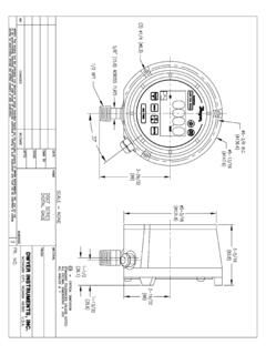
2 19 Wiring, Intrinsic Safety and Warnings.. 20-22 Schematics: General and Intrinsic Safety.. 23-27 Maintenance .. 28 DIMENSIONSCLEARANCE REQUIREDFOR COVER REMOVALLEVER DRIVE1-1/16[ ]5/16[ ].249 .001[ .03]2-3/8[ ]DIRECTDRIVE4-1/4[ ]3[ ]5-15/16[ ]*4-9/16[ ]1-1/4[ ]#6-32 UNCTHREADX 1/4 [ ]DEEP1-9/16[ ]4-7/8[ ]3/4 NPTCONDUITCONNECTIONOR OPTIONALM25 X [ ]2-3/8[ ] 4-7/16[ ]1/4[ ]TYP 1/8 [ ] PIN TYP 2 PLACES1/2 NPT CONDUIT CONNECTION [OPTIONAL]OR OPTIONAL M20 X 2 PLACES1/4-20 UNC THREADX 7/16 [ ] DPTYP 2 PLACES*FOR MODELS 11, 12, 41 & 42 118 1-1/2[ ]OPENHART & WirelessHART are registered trademarks of HART Communication [ ]118 DIRECTDRIVELEVERDRIVEANTENNA1/4-20 UNCTHREADX 7/16 [ ] DPTYP 2 PLACES1/2 NPT CONDUIT CONNECTION[OPTIONAL] OR OPTIONAL M20 X 2 PLACES1/8 [ ]PIN TYP 2 PLACES#6-32 UNCTHREADX 1/4 [ ] DPCLEARANCEREQUIREDFOR.
3 001[ .03]2-3/8[ ]5/16[ ]1-1/16[ ]4-1/4[ ]5-15/16[ ]1-1/4 [ ]4-7/8[ ]2-3/8[ ]6-11/16[ ]1-1/2[ ]4-7/16[ ]1/4[ ]TYP1[ ] 2 INTRODUCTIONThe Proximity Controls Mark Series is a line of Position indicators with a selection of various output options. Threemodel styles make up the Mark Series to cover almost any application. A magnetic drive that completely seals theswitch compartment from the atmosphere for maximum leak protection is utilized in the Mark 1. The Mark 3 uses thesame magnetic drive of the Mark 1, but it can be used for multi-turn applications with 1 to 25 revolutions, such as gatevalves. A through shaft drive is incorporated in the Mark 4 making the unit a lower cost alternative to the Mark 1 forapplications that are not as demanding. Standard models in the Mark Series have visual Position indicators and are weatherproof, flameproof, and large variety of outputs are available to fit specific applications.
4 There is a choice of 1 to 6 switch outputs of 13varieties including inductive sensors, high temperature switches, gold contact switches, hermetically sealed switches,and high current switches. Aside from switch outputs, the Mark Series offers potentiometer outputs, 4 to 20 mAtransmitters, and both HART and WirelessHART units are purchased for either direct drive applications, such as rotary valves, or lever drive applications, such aslinear valves. For the Mark 1, 3, and 4 this instruction manual starts with installation of the unit to the device beingmonitored, and the set up of switch models. Separate instructions follow covering the potentiometer and transmitter setup if your unit has those options. This product uses FreeRTOS ( ) version A copy of the original FreeRTOS source shall beprovided upon Ratings:Weatherproof and flameproof.
5 NEMA 1, 2, 3, 3R, 3S, 4, 4X, 6, 7, 9, 12, rated: Class I, Div. 1 & 2, Groups B, C, D (Some units available for Group A, consult factory); Class II, Div. 1 & 2,Groups E, F, and G. CSA rated: Class I, Div. 1 & 2, Groups A, B, C, D; Class II, Div. 1 & 2, Groups E, F, and G. Submersible to 15 meters(IP68); It is up to the end user to source the proper fittings to ensure a watertight Compliant: -B suffix, any Output Type except 91: Directive 2014/34/EU, KEMA 03 ATEX2391 X, 0518 II 2G Ex db IIC T6Gb for -25 C/-40 C/-50 C Tamb 63 C depending on output and switch type selected. Compliant per EN 60079-0:2012+A11:2013 and EN 60079-1 suffix, Output Type 91, with or without -LB suffix: Directive 2014/34/EU, KEMA 03 ATEX2391 X, 0518 II 2 GEx db ib IIC T4 Gb for -40 C Tamb 65 C.
6 Compliant per EN 60079-0:2012 + A11:2013, EN 60079-1:2014 andEN 60079-11 suffix, any Output Type except 91: Directive 2014/34/EU, KEMA 03 ATEX1392 X, 0518 II 1G Ex ia IIC T4Ga. Compliant per EN 60079-0:2012 + A11: 2013 and EN 60079-11 suffix, Output Type 91, with or without -LB suffix: Directive 2014/34/EU, KEMA 03 ATEX1392 X, 0518 II 2 GEx ia IIC T4 Ga. Compliant per EN 60079-0:2012+A11:2013 and EN 60079-11 Compliant:-IE suffix, any Output Type except 91:IECEx DEK Ex db IIC T6 Gb for -25 C/-40 C/-50 C Tamb 63 Cdepending on output and switch type selected. Compliant per IEC 60079-0:2011 and IEC 60079-1 suffix, Output Type 91, with or without -LB suffix: IECEx DEK , Ex db ib IIC T4 Gb for -40 Tamb 65 C. Compliant per IEC 60079-0:2011, IEC 60079-1:2014 and IEC 60079-11: suffix, any Output Type except 91: IECEx DEK Ex ia IIC T4 Ga.
7 Compliant per IEC 60079-0:2011, IEC60079-11:2011, and IEC 60079-26 suffix, Output Type 91, with or without -LB suffix: DEK Ex ia IIC T4 Ga. Compliant per IEC 60079-0:2014, and IEC 60079-11 Compliant:IM suffix, Certificate: NCC X; Marking: Ex ia IIC T4 GaABNT NBR IEC 60079-0; ABNT NBR IEC 60079-11 e ABNT NBR IEC 60079-26EM suffix, Certifcate: NCC X; Marking: Ex d IIC T6 Gb or Ex d IIC T5 GbABNT NBR IEC 60079-0 e ABNT NBR IEC 60079-1 Electrical Connections:Screw terminal. Optional factory sealed leads that are 36 ( mm) of 16 Connection:Standard: one 3/4 female NPT; optional one to two 1/2 female NPT; WirelessHART models:two 1/2 female NPT; Optional: M25 X or M20 X connections may be supplied in lieu of 3/4 and 1/2 femaleNPT for all Orientation:Not Position :4 to 6 lb ( to kg).
8 Operational Life: Over 10,000,000 Altitude:2000 1, 3 and 4 with Switch Outputs4 Temperature Limits:-58 to 176 F (-50 to 80 C). Switch Type C rated to 350 F (176 C) for 600 hours, Switch Type Trated to 250 F (121 C) continuous. (ATEX flameproof, -B suffix and IECEx flameproof, -IE suffix, rated -58to 145 F(-50 to 63 C) for switch type A, G, H, T, or M, -40 to 145 F (-40to 63 C) for switch type O, R, S, V, or W, -13to145 F (-25to 63 C) for switch type B, D, I, or AS Interface; ATEX intrinsically safe, -IS suffix and IECEx intrinsicallysafe, -II suffix, rated -13 to 104 F (-25 to 40 C) for switch type D or I, -40to 104 F (-40to 40 C) for switch type R, V,or W, or -58to 104 F (-50 to 40 C) for switch type A, G, or H.)Switch Type:See model chart on pages 5 and Rating: See model chart on pages 5 and Point Adjustment:Mark 1 and 4: 5 to 360.
9 Mark 3: 1 to 25 1, 3, and 4 with PotentiometerAccuracy: of full span. Optional of full Limits:-40 to 176 F (-40 to 80 C).(ATEX flameproof, -B suffix and IECEx flameproof, -IE suffix, rated -40 to 145 F (-40 to 63 C) for switch types A, G, M, O, R, S, T, V, or W, -13 to 145 F (-25 to 63 C) for switch typesB, D, or I.; ATEX intrinsically safe, -IS suffix and IECEx intrinsically safe, -II suffix, rated -13to 104 F (-25 to 40 C) forswitch type I, -40 to 104 F (-40 to 40 C) for switch types O, R, S, V, or Watt maximum. Output Signal:1000 standard. Optional 2000, 5000, 10000, or 20000 .Zero and Span Adjustments:Span trim pot with 2000 adjustment. No zero Travel:Mark 1 and 4: Minimum: 0 , Maximum: 340 . Mark 3: 0 to 10 1, 3, and 4 with TransmitterAccuracy: of full span.)
10 Optional of full Limits: -40 to 176 F (-40 to 80 C). (ATEX flameproof, -B suffix and IECEx flameproof, -IE suffix, rated-40 to 145 F (-40 to 63 C) for switch types A, G, M, O, R, S, T, V, or W, -13to 145 F (-25 to 63 C) for switch typesB, D, or I.; ATEX intrinsically safe, -IS suffix and IECEx intrinsically safe, -II suffix, rated -13to 104 F (-25 to 40 C) forswitch type I, -40to 104 F (-40to 40 C) for switch types O, R, S, V, or W.)Power Requirements:5 to 30 Consumption:50 mA. Output Signal: 4 to 20 and Span Adjustments:Trim pots for adjusting both. Mark 1 and 4: Span is adjustable from 50 to 300 . Mark3: Span is adjustable from to revolutions. Conduit Connection:3/4 female NPT standard. Optional one or two 1/2 female NPT. M25 X and M20 X Travel:Mark 1 and 4: Minimum: 50 , Maximum: 300.