Transcription of MAX9259/MAX9260 Gigabit Multimedia Serial Link with …
1 Gigabit Multimedia Serial Link with Spread spectrum and Full-Duplex Control ChannelMAX9259/MAX9260 EVALUATION KIT AVAILABLE19-4968; Rev 4; 10/14 Typical Applications Circuit appears at end of data sheet. General DescriptionThe MAX9259 serializer pairs with the MAX9260 deseri-alizer for joint transmission of high-speed video, audio, and control MAX9259/MAX9260 operate up to for a 15m shielded twisted-pair (STP) cable. This Serial link supports display panels from QVGA (320 x 240) up to XGA (1280 x 768), or dual-view WVGA (2 x 854 x 480).The embedded audio channel supports I2S up to 32 bits per sample and at a 192kHz sample rate.
2 The embed-ded control channel forms a full-duplex, differential 100kbps to 1 Mbps UART link between the serializer and deserializer. The host electronic control unit (ECU) or microcontroller (FC) resides either on the MAX9259 or on the MAX9260. In addition, the control channel enables ECU/FC control of peripherals in the remote side of the Serial link through I2 and channel equalization extend the link length and enhance the link reliability. Spread spectrum is available to reduce EMI on the Serial and parallel out-put data signals. The differential link complies with the ISO 10605 and IEC 61000-4-2 ESD-protection core supplies for the MAX9259/MAX9260 are and , respectively.
3 Both devices use an I/O sup-ply from to These devices are available in a 64-pin TQFP package (10mm x 10mm) and a 56-pin TQFN/QFND package (8mm x 8mm x ) with an exposed pad. Electrical performance is guaranteed over the -40NC to +105NC automotive temperature range. ApplicationsHigh-Resolution Automotive NavigationRear-Seat InfotainmentMegapixel Camera Systems FeaturesS Ideal for Digital Video Applications Up to XGA (1280 x 768) or Dual-View WVGA (2 x 854 x 480) Panels with 18- or 24-Bit Color Pre/Deemphasis Allows 15m Cable at Full Speed Up to 192kHz.
4 32-Bit Sample I2SS Multiple Data Rates for System Flexibility Up to Serial -Bit Rate to 104 MHz Pixel Clock Up to 1 Mbps UART/UART-to-I2C Control ChannelS Reduces EMI and Shielding Requirements Serial Output Programmable for 100mV to 400mV Programmable Spread spectrum Reduces EMI Bypasses Input PLL for Jitter AttenuationS Peripheral Features for System Verification Built-In Serial Link PRBS BER Tester Interrupt Transmission from Deserializer to Serializer Meets AEC-Q100 Requirements -40NC to +105NC Operating Temperature Range 10kV Contact and 25kV Air ISO 10605 and 10kV IEC 61000-4-2 ESD Protection Ordering Information/V denotes an automotive qualified part.
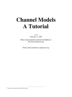
5 +Denotes a lead(Pb)-free/RoHS-compliant package.*EP = Exposed = Tape and reel. Simplified Diagram CMAX9259 MAX9260 VIDEO/AUDIOI2C720pDISPLAYVIDEO/AUDIOI2 CPARTTEMP RANGEPIN-PACKAGEMAX9259 GCB/V+-40NC to +105NC64 TQFP-EP*MAX9259 GCB/V+T-40NC to +105NC64 TQFP-EP*MAX9259 GTN/V+T-40NC to +105NC56 TQFN-EP*MAX9259 GGN/VY+-40NC to +105NC56 QFND-EP*MAX9260 GCB/V+-40NC to +105NC64 TQFP-EP*MAX9260 GCB/V+T-40NC to +105NC64 TQFP-EP*For pricing, delivery, and ordering information, please contact Maxim Direct at 1-888-629-4642, or visit Maxim s website at Maxim IntegratedGigabit Multimedia Serial Link with Spread spectrum and Full-Duplex Control ChannelMAX9259/MAX9260 Stresses beyond those listed under Absolute Maximum Ratings may cause permanent damage to the device.
6 These are stress ratings only, and functional operation of the device at these or any other conditions beyond those indicated in the operational sections of the specifications is not implied. Exposure to absolute maximum rating conditions for extended periods may affect device to AGND MAX9259 .. to + MAX9260 .. to + to GND (MAX9259) .. to + to DGND (MAX9260) .. to + to GND (MAX9259) .. to + to IOGND (MAX9260) .. to + Ground to Any Ground .. to + +, OUT- to AGND (MAX9259) .. to + +, IN- to AGND (MAX9260) .. to + to GND (MAX9259) (60kI source impedance) .. to + Other Pins to GND (MAX9259).
7 To (IOVDD + )All Other Pins to IOGND (MAX9260) .. to (IOVDD + )OUT+, OUT- Short Circuit to Ground or Supply (MAX9259) ..ContinuousIN+, IN- Short Circuit to Ground or Supply (MAX9260) ..ContinuousContinuous Power Dissipation (TA = +70NC) 64-Pin TQFP (derate above +70NC) ..2508mW 56-Pin TQFN (derate above +70NC) .. 56-Pin QFND (derate above +70NC) ..3148mWOperating Temperature Range ..-40NC to +105 NCJunction Temperature ..+150 NCStorage Temperature Range ..-65NC to +150 NCLead Temperature (soldering, 10s) ..+300 NCSoldering Temperature (reflow) ..+260 NCMAX9259 DC ELECTRICAL CHARACTERISTICS(VDVDD = VAVDD = to , VIOVDD = to , RL = 100I Q1% (differential), TA = -40NC to +105NC, unless otherwise noted.)
8 Typical values are at VDVDD = VAVDD = VIOVDD = , TA = +25NC.)ABSOLUTE MAXIMUM RATINGS64 TQFP Junction-to-Ambient Thermal Resistance (BJA) .. Junction-to-Case Thermal Resistance (BJC) ..1NC/W56 TQFN Junction-to-Ambient Thermal Resistance (BJA) ..21NC/W Junction-to-Case Thermal Resistance (BJC) ..1NC/W56 QFND Junction-to-Ambient Thermal Resistance (BJA) .. Junction-to-Case Thermal Resistance (BJC) .. THERMAL CHARACTERISTICS (Note 1)Note 1: Package thermal resistances were obtained using the method described in JEDEC specification JESD51-7, using a four-lay-er board. For detailed information on package thermal considerations, refer to INPUTS (DIN_, PCLKIN, PWDN, SSEN, BWS, ES, DRS, MS, CDS, AUTOS, SD, SCK, WS)High-Level Input xVIOVDDVLow-Level Input x VIOVDDVI nput CurrentIIN1 VIN = 0 to VIOVDD-10+10 FAInput Clamp VoltageVCLICL = OUTPUT (INT)High-Level Output VoltageVOH1 IOH = -2mAVIOVDD - Output VoltageVOL1 IOL = Short-Circuit CurrentIOSVO = 0 VVIOVDD = to = to 3 Maxim IntegratedGigabit Multimedia Serial Link with Spread spectrum and Full-Duplex Control ChannelMAX9259/MAX9260 MAX9259 DC ELECTRICAL CHARACTERISTICS (continued)
9 (VDVDD = VAVDD = to , VIOVDD = to , RL = 100I Q1% (differential), TA = -40NC to +105NC, unless otherwise noted. Typical values are at VDVDD = VAVDD = VIOVDD = , TA = +25NC.)PARAMETERSYMBOLCONDITIONSMINTYPMA XUNITSI2C AND UART I/O, OPEN-DRAIN OUTPUTS (RX/SDA, TX/SCL, LFLT)High-Level Input x VIOVDDVLow-Level Input x VIOVDDVI nput CurrentIIN2 VIN = 0 to VIOVDD (Note 2)-110+5 FALow-Level Open-Drain Output VoltageVOL2 IOL = 3mAVIOVDD = to = to OUTPUT (OUT+, OUT-)Differential Output VoltageVODP reemphasis off (Figure 1) preemphasis setting, VOD(P) (Figure 2) deemphasis setting, VOD(D) (Figure 2)240425 Change in VOD Between Complementary Output StatesDVOD15mVOutput Offset Voltage, (VOUT+ + VOUT-)
10 /2 = VOSVOSP reemphasis in VOS Between Complementary Output StatesDVOS15mVOutput Short-Circuit CurrentIOSVOUT+ or VOUT- = 0V-60mAVOUT+ or VOUT- = of Differential Output Short-Circuit CurrentIOSDVOD = 0V25mAOutput Termination Resistance (Internal)ROFrom OUT+, OUT- to VAVDD455463 IREVERSE CONTROL-CHANNEL RECEIVER (OUT+, OUT-)High Switching ThresholdVCHR27mVLow Switching ThresholdVCLR-27mVLINE-FAULT-DETECTION INPUT (LMN_)Short-to-GND ThresholdVTGF igure ThresholdsVTNF igure ThresholdsVTOF igure + Input VoltageVIOF igure ThresholdVTEF igure SUPPLYW orst-Case Supply Current (Figure 4)IWCSBWS = GNDfPCLKIN = = = = 104 MHz135175 Sleep-Mode Supply CurrentICCS40110 FAPower-Down Supply CurrentICCZPWDN = GND570FA4 Maxim IntegratedGigabit Multimedia Serial Link with Spread spectrum and Full-Duplex Control ChannelMAX9259/MAX9260 MAX9259 DC ELECTRICAL CHARACTERISTICS (continued)(VDVDD = VAVDD = to , VIOVDD = to , RL = 100I Q1% (differential), TA = -40NC to +105NC, unless otherwise noted.)