Transcription of MCP1826/MCP1826S Data Sheet - Microchip Technology
1 2007-2013 Microchip Technology 1 mcp1826 / mcp1826 SFeatures: 1000 mA Output Current Capability Input Operating voltage Range: to adjustable Output voltage Range: to ( mcp1826 only) Standard fixed Output Voltages:- , , , , , , Other fixed Output voltage Options Available Upon Request Low Dropout voltage : 250 mV Typical at 1000 mA Typical Output voltage Tolerance: Stable with F Ceramic Output Capacitor Fast Response to Load Transients Low Supply Current: 120 A (typ) Low Shutdown Supply Current: A (typ) ( mcp1826 only) fixed Delay on Power Good Output( mcp1826 only) Short Circuit Current Limiting and Overtemperature Protection TO-263-5 (DDPAK-5), TO-220-5, SOT-223-5 Package Options ( mcp1826 ).
2 TO-263-3 (DDPAK-3), TO-220-3, SOT-223-3 Package Options ( mcp1826s ).Applications: High-Speed Driver Chipset Power Networking Backplane Cards Notebook Computers Network Interface Cards Palmtop ComputersDescription:The MCP1826/MCP1826S is a 1000 mA Low Dropout(LDO) linear regulator that provides high-current andlow-output voltages. The mcp1826 comes in a fixed oradjustable output voltage version, with an outputvoltage range of to The 1000 mA output cur-rent capability, combined with the low-output voltagecapability, make the mcp1826 a good choice for output voltage LDO applications that havehigh current demands.
3 The mcp1826s is a 3-pin fixedvoltage MCP1826/MCP1826S is stable using ceramicoutput capacitors that inherently provide lower outputnoise and reduce the size and cost of the entireregulator solution. Only 1 F of output capacitance isneeded to stabilize the LDO. Using CMOS construction, the quiescent currentconsumed by the MCP1826/MCP1826S is typicallyless than 120 A over the entire input voltage range,making it attractive for portable computing applicationsthat demand high-output current. The MCP1826versions have a Shutdown (SHDN) pin. When shutdown, the quiescent current is reduced to less the mcp1826 fixed output versions the scaled-down output voltage is internally monitored and apower good (PWRGD) output is provided when theoutput is within 92% of regulation (typical).
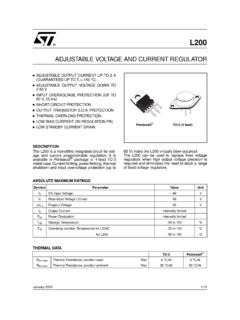
4 ThePWRGD delay is internally fixed at 200 s (typical).The overtemperature and short circuit current-limitingprovide additional protection for the LDO during systemFault conditions. 1000 mA, Low- voltage , Low Quiescent CurrentLDO RegulatorMCP1826/ mcp1826 SDS22057B-page 2 2007-2013 Microchip Technology TypesMCP1826123456 SOT-223-5 PinFixedAdjustable1 SHDNSHDN2 VINVIN3 GND (TAB)GND (TAB)4 VOUTVOUT5 PWRGD ADJ6 GND (TAB)GND (TAB)123 SOT-223-34 mcp1826 SPin1 VIN2 GND (TAB)3 VOUT4 GND (TAB) fixed /AdjustableDDPAK-3 DDPAK-5TO-220-3TO-220-51234512345123123 2007-2013 Microchip Technology 3 mcp1826 / mcp1826 STypical ApplicationMCP1826 adjustable Output VoltageMCP1826 fixed Output VoltageVOUT = @ 1000 mAVIN = to F100 k FC1C2R1 SHDNVINGNDVOUTPWRGD20 k R2 VOUT = @ 1000 mAVIN = to F40 k FC1C2R1 SHDNVINGNDVOUTVADJ11 mcp1826 / mcp1826 SDS22057B-page 4 2007-2013 Microchip Technology Block Diagram adjustable OutputEA+ VOUTPMOSRfCfISNSO vertemperatureVREFComp92% of VREFTDELAYVIND river w/limitand SHDNGNDSoft-StartADJ/SENSEU ndervoltage LockoutVINR eferenceSHDNSHDNSHDNS ensing(UVLO)
5 2007-2013 Microchip Technology 5 mcp1826 / mcp1826 SFunctional Block Diagram fixed Output (3-Pin)EA+ VOUTPMOSRfCfISNSO vertemperatureVREFComp92% of VREFTDELAYVIND river w/limitand SHDNGNDSoft-StartSenseUndervoltage LockoutVINR eferenceSHDNSHDNSHDNS ensing(UVLO) mcp1826 / mcp1826 SDS22057B-page 6 2007-2013 Microchip Technology Block Diagram fixed Output (5-Pin)EA+ VOUTPMOSRfCfISNSO vertemperatureVREFComp92% of VREFVIND river w/limitand SHDNGNDSoft-StartSenseUndervoltage LockoutVINR eferenceSHDNSHDNSHDNS ensing(UVLO)PWRGDTDELAY 2007-2013 Microchip Technology 7 mcp1826 CHARACTERISTICSA bsolute Maximum Ratings voltage on Any Pin.
6 (GND ) to (VDD + )VMaximum Power Internally-Limited (Note 6)Output Short Circuit Duration .. ContinuousStorage temperature ..-65 C to +150 CMaximum Junction Temperature, +150 CESD protection on all pins (HBM/MM) 4kV; 300V Notice: Stresses above those listed under MaximumRatings may cause permanent damage to the device. This isa stress rating only and functional operation of the device atthose or any other conditions above those indicated in theoperational listings of this specification is not implied. Expo-sure to maximum rating conditions for extended periods mayaffect device CHARACTERISTICSE lectrical Specifications.
7 Unless otherwise noted, VIN = VOUT(MAX) + VDROPOUT(MAX), Note 1, VR= for adjustable Output, IOUT = 1 mA, CIN = COUT = F (X7R Ceramic), TA = +25 type applies for junction temperatures, TJ (Note 7) of -40 C to +125 C Operating 1 Input Quiescent CurrentIq 120220 AIL = 0 mA, VOUT = to Quiescent Current for SHDN ModeISHDN ASHDN = GNDM aximum Output CurrentIOUT1000 mAVIN = to = to , Note 1 Line Regulation VOUT/(VOUT x VIN) (Note 1) VIN 6 VLoad Regulation = 1 mA to 1000 mA, (Note 4)Output Short Circuit CurrentIOUT_SC ARLOAD< , Peak CurrentAdjust Pin Characteristics ( adjustable Output Only)Adjust Pin Reference = to VIN= ,IOUT = 1 mAAdjust Pin Leakage CurrentIADJ-10 +10nAVIN = , VADJ=0 Vto6 VAdjust Temperature CoefficientTCVOUT 40 ppm/ CNote 3 fixed -Output Characteristics ( fixed Output Only) voltage RegulationVOUTVR - + 2 Note 1:The minimum VIN must meet two conditions: VIN and VIN VOUT(MAX) VDROPOUT(MAX).
8 2:VR is the nominal regulator output voltage for the fixed cases. VR = , , etc. VR is the desired set point output voltage for the adjustable cases. VR = VADJ * ((R1/R2)+1). Figure :TCVOUT = (VOUT-HIGH VOUT-LOW) *106 / (VR * Temperature). VOUT-HIGH is the highest voltage measured over the temperature range. VOUT-LOW is the lowest voltage measured over the temperature :Load regulation is measured at a constant junction temperature using low duty-cycle pulse testing. Load regulation is tested over a load range from 1 mA to the maximum specified output :Dropout voltage is defined as the input-to-output voltage differential at which the output voltage drops 2% below its nominal value that was measured with an input voltage of VIN = VOUT(MAX) + VDROPOUT(MAX).
9 6:The maximum allowable power dissipation is a function of ambient temperature, the maximum allowable junction temperature and the thermal resistance from junction to air. ( , TA, TJ, JA). Exceeding the maximum allowable power dissipation will cause the device operating junction temperature to exceed the maximum +150 C rating. Sustained junction temperatures above 150 C can impact device :The junction temperature is approximated by soaking the device under test at an ambient temperature equal to the desired junction temperature. The test time is small enough such that the rise in the junction temperature over the ambient temperature is not 8 2007-2013 Microchip Technology CharacteristicsDropout VoltageVDROPOUT 250400mVNote 5, IOUT = 1000 mA, VIN(MIN)= Good CharacteristicsPWRGD Input voltage Operat-ing Range = +25 = -40 C to +125 CFor VIN < , ISINK=100 APWRGD Threshold voltage (Referenced to VOUT)
10 VPWRGD_TH%VOUTF alling Edge899295 VOUT < fixed ,VOUT = >= FixedPWRGD Threshold Output voltage LowVPWRGD_L SINK = mA,ADJ = 0 VPWRGD LeakagePWRGD_LK 1 nAVPWRGD = VIN = Time DelayTPG 125 sRising EdgeRPULLUP = 10 k Detect Threshold to PWRGD Active Time DelayTVDET-PWRGD 200 sVOUT = VPWRGD_TH + 20 mV to VPWRGD_TH - 20 mVShutdown InputLogic High Input VSHDN-HIGH45 %VINVIN = to Low Input VSHDN-LOW 15%VINVIN = to Input Leakage + AVIN=6V, SHDN =VIN,SHDN = GNDAC PerformanceOutput Delay From SHDNTOR 100 sSHDN = GND to VIN VOUT = GND to 95% VR Output NoiseeN V/ Hz IOUT = 200 mA, f = 1 kHz, COUT = 10 F (X7R Ceramic), VOUT = CHARACTERISTICS (CONTINUED)Electrical Specifications: Unless otherwise noted, VIN = VOUT(MAX) + VDROPOUT(MAX), Note 1, VR= for adjustable Output, IOUT = 1 mA, CIN = COUT = F (X7R Ceramic), TA = +25 type applies for junction temperatures, TJ (Note 7) of -40 C to +125 C 1:The minimum VIN must meet two conditions: VIN and VIN VOUT(MAX) VDROPOUT(MAX).