Transcription of MCP23017/MCP23S17 Data Sheet - Microchip Technology
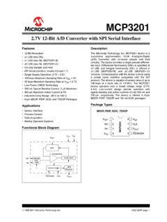
1 MCP23017/MCP23S17 . 16-Bit I/O Expander with serial Interface Features Configurable Interrupt Source: - Interrupt-on-change from configured register 16-Bit Remote Bidirectional I/O Port: defaults or pin changes - I/O pins default to input Polarity Inversion Register to Configure the High-Speed I2C Interface ( mcp23017 ): Polarity of the input Port Data - 100 kHz External Reset input - 400 kHz Low Standby Current: 1 A (max.). - MHz Operating voltage : High-Speed SPI Interface (MCP23S17): - to @ -40 C to +85 C. - 10 MHz (maximum) - to @ -40 C to +85 C. Three Hardware Address Pins to Allow Up to - to @ -40 C to +125 C. Eight Devices On the Bus Configurable Interrupt Output Pins: Packages - Configurable as active-high, active-low or open-drain 28-pin QFN, 6 x 6 mm Body INTA and INTB Can Be Configured to Operate 28-pin SOIC, Wide, mm Body Independently or Together 28-pin SPDIP, 300 mil Body 28-pin SSOP, mm Body Package Types mcp23017 MCP23S17. GPB0 1 28 GPA7 GPB0 1 28 GPA7. GPB1 2 27 GPA6 GPB1 2 27 GPA6.
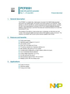
2 GPB2 3 26 GPA5 GPB2 3 26 GPA5. GPB3 4 25 GPA4 GPB3 4 25 GPA4. GPB4 5 24 GPA3 GPB4 5 24 GPA3. GPB5 6 23 GPA2 GPB5 6 23 GPA2. GPB6 7 22 GPA1 SOIC 7 22 GPA1. GPB6. GPB7 8 21 GPA0 SPDIP GPB7 8 21 GPA0. VDD 9 20 INTA SSOP VDD 9 20 INTA. VSS 10 19 INTB VSS 10 19 INTB. NC 11 18 RESET 11 18. CS RESET. SCK 12 17 A2 SCK 12 17 A2. SDA 13 16 A1 SI 13 16 A1. NC 14 15 A0 SO 14 15 A0. GPB3. GPB2. GPB1. GPB0. GPA7. GPA6. GPA5. GPB3. GPB2. GPB1. GPB0. GPA7. GPA6. GPA5. 28 2726 2524 2322 28 2726 25 24 23 22. GPB4 1 21 GPA4 GPB4 1 21 GPA4. GPB5 2 20 GPA3 GPB5 2 20 GPA3. GPB6 3 19 GPA2 QFN GPB6 3 19 GPA2. EP EP. GPB7 4 18 GPA1 GPB7 4 18 GPA1. VDD 29 * 29 *. 5 17 GPA0 VDD 5 17 GPA0. VSS 6 16 INTA VSS 6 16 INTA. NC 7 15 INTB CS 7 15 INTB. 8 9 1011 121314 8 9 10 11 121314. SDA. NC. A0. A1. A2. RESET. SI. A0. A1. A2. RESET. SO. SCK. SCK. * Includes Exposed Thermal Pad; see Table 2-1. 2005-2016 Microchip Technology Inc. DS20001952C-page 1. MCP23017/MCP23S17 . Functional Block Diagram MCP23S17. CS. SCK. SI. SO SPI.
3 mcp23017 . GPB7. SCL Serializer/. 2. I C Deserializer GPB6. SDA. GPB5. GPB4. 3 GPIO. A2:A0 Decode GPB3. GPB2. RESET Control GPB1. INTA Interrupt 16 GPB0. INTB Logic GPA7. GPA6. 8 GPA5. GPA4. GPIO GPA3. Configuration/ GPA2. Control GPA1. Registers GPA0. DS20001952C-page 2 2005-2016 Microchip Technology Inc. MCP23017/MCP23S17 . ELECTRICAL CHARACTERISTICS. Absolute Maximum Ratings . Ambient temperature under C to +125 C. Storage temperature ..-65 C to +150 C. voltage on VDD with respect to VSS .. to + voltage on all other pins with respect to VSS (except VDD).. to (VDD + ). Total power mW. Maximum current out of VSS pin ..150 mA. Maximum current into VDD pin ..125 mA. input clamp current, IIK (VI < 0 or VI > VDD).. 20 mA. Output clamp current, IOK (VO < 0 or VO > VDD).. 20 mA. Maximum output current sunk by any output pin ..25 mA. Maximum output current sourced by any output pin ..25 mA. ESD protection on all pins (HBM:MM) ..4 kV:400V. Notice: Stresses above those listed under Maximum Ratings may cause permanent damage to the device.
4 This is a stress rating only and functional operation of the device at those or any other conditions above those indicated in the operational listings of this specification is not implied. Exposure to maximum rating conditions for extended periods may affect device reliability. 2005-2016 Microchip Technology Inc. DS20001952C-page 3. MCP23017/MCP23S17 . DC Characteristics TABLE 1-1: DC CHARACTERISTICS. Electrical Specifications: Unless otherwise noted, VDD at -40 C TA +125 C. Param. Characteristic Sym. Min. Typ.(1) Max. Units Conditions No. D001 Supply voltage VDD V. D002 VDD Start voltage to VPOR VSS V. ensure Power-on Reset D003 VDD Rise Rate to ensure SVDD V/ms Design guidance only. Power-on Reset Not tested. D004 Supply Current IDD 1 mA SCL/SCK = 1 MHz D005 Standby current IDDS8 1 A -40 C TA +85 C. 3 A VDD +85 C TA +125 C. (Note 1). input Low voltage D030 A0, A1, A2 (TTL buffer) VIL VSS VDD V. D031 CS, GPIO, SCL/SCK, VIL VSS VDD V. SDA, RESET. (Schmitt Trigger). input High voltage D040 A0, A1, A2 (TTL buffer) VIH VDD + VDD V.
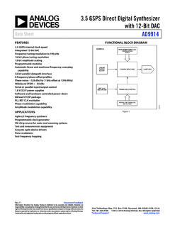
5 D041 CS, GPIO, SCL/SCK, VIH VDD VDD V For entire VDD range SDA, RESET. (Schmitt Trigger). input Leakage Current D060 I/O port pins IIL 1 A VSS VPIN VDD. Output Leakage Current D065 I/O port pins ILO 1 A VSS VPIN VDD. D070 GPIO weak pull-up IPU 40 75 115 A VDD = 5V. current GP pins = VSS. Output Low- voltage D080 GPIO VOL V IOL = mA. VDD = INT VOL V IOL = mA. VDD = SO, SDA VOL V IOL = mA. VDD = SDA VOL V IOL = mA. VDD = Output High- voltage D090 GPIO, INT, SO VOH VDD V IOH = mA. VDD = VDD IOH = -400 A. VDD = Capacitive Loading Specs on Output Pins D101 GPIO, SO, INT CIO 50 pF. D102 SDA CB 400 pF. Note 1: This parameter is characterized, not 100% tested. DS20001952C-page 4 2005-2016 Microchip Technology Inc. MCP23017/MCP23S17 . AC Characteristics FIGURE 1-1: LOAD CONDITIONS FOR DEVICE TIMING SPECIFICATIONS. VDD. Pin 1 k . SCL and 50 pF. SDA pin mcp23017 . 135 pF. FIGURE 1-2: RESET AND DEVICE RESET TIMER TIMING. VDD. RESET. 30 32. Internal RESET. 34. Output pin TABLE 1-2: DEVICE RESET SPECIFICATIONS.
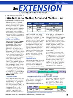
6 AC Characteristics: Unless otherwise noted, VDD at -40 C TA +125 C. Param. Characteristic Sym. Min. Typ. (1) Max. Units Conditions No. 30 RESET Pulse Width TRSTL 1 s (Low). 32 Device Active After Reset THLD 0 ns VDD = high 34 Output High-Impedance TIOZ 1 s From RESET Low Note 1: This parameter is characterized, not 100% tested. 2005-2016 Microchip Technology Inc. DS20001952C-page 5. MCP23017/MCP23S17 . FIGURE 1-3: I2C BUS START/STOP BITS TIMING. SCL. 91 93. 90 92. SDA. Start Stop Condition Condition FIGURE 1-4: I2C BUS DATA TIMING. 103 100 102. 101. SCL. 90 106. 91 107 92. SDA. In 109 109 110. SDA. Out TABLE 1-3: I2C BUS DATA REQUIREMENTS. I2C Interface AC Characteristics: Unless otherwise noted, VDD at -40 C TA +125 C, RPU (SCL, SDA) = 1 k , CL (SCL, SDA) = 135 pF. Param. Characteristic Sym. Min. Typ. Max. Units Conditions No. 100 Clock High Time: THIGH. 100 kHz mode s 400 kHz mode s MHz mode s 101 Clock Low Time: TLOW. 100 kHz mode s 400 kHz mode s MHz mode s 102 SDA and SCL Rise Time: TR (1).
7 100 kHz mode 1000 ns (2). 400 kHz mode 20 + CB 300 ns MHz mode 20 160 ns 103 SDA and SCL Fall Time: TF (1). 100 kHz mode 300 ns (2). 400 kHz mode 20 + CB 300 ns MHz mode 20 80 ns Note 1: This parameter is characterized, not 100% tested. 2: CB is specified to be from 10 to 400 pF. DS20001952C-page 6 2005-2016 Microchip Technology Inc. MCP23017/MCP23S17 . TABLE 1-3: I2C BUS DATA REQUIREMENTS (CONTINUED). I2C Interface AC Characteristics: Unless otherwise noted, VDD at -40 C TA +125 C, RPU (SCL, SDA) = 1 k , CL (SCL, SDA) = 135 pF. Param. Characteristic Sym. Min. Typ. Max. Units Conditions No. 90 START Condition Setup Time: TSU:STA. 100 kHz mode s 400 kHz mode s MHz mode s 91 START Condition Hold Time: THD:STA. 100 kHz mode s 400 kHz mode s MHz mode s 106 Data input Hold Time: THD:DAT. 100 kHz mode 0 s 400 kHz mode 0 s MHz mode 0 s 107 Data input Setup Time: TSU:DAT. 100 kHz mode 250 ns 400 kHz mode 100 ns MHz mode s 92 Stop Condition Setup Time: TSU:STO. 100 kHz mode s 400 kHz mode s MHz mode s 109 Output Valid From Clock: TAA.
8 100 kHz mode s 400 kHz mode s MHz mode s 110 Bus Free Time: TBUF. 100 kHz mode s 400 kHz mode s MHz mode N/A N/A s 111 Bus Capacitive Loading: CB. 100 kHz and 400 kHz 400 pF Note 1. MHz 100 pF Note 1. 112 input Filter Spike Suppression TSP. (SDA and SCL): 100 kHz and 400 kHz 50 ns MHz 10 ns Spike suppression off Note 1: This parameter is characterized, not 100% tested. 2: CB is specified to be from 10 to 400 pF. 2005-2016 Microchip Technology Inc. DS20001952C-page 7. MCP23017/MCP23S17 . FIGURE 1-5: SPI input TIMING. 3. CS (1). 11. 1 6 10. Mode 1,1 7 2. SCK Mode 0,0. 4 5. SI. MSB in LSB in SO High-Impedance Note 1: When using SPI Mode 1,1 the CS pin needs to be toggled once before the first communication after power-up. FIGURE 1-6: SPI OUTPUT TIMING. CS. 2. 8 9. SCK Mode 1,1. Mode 0,0. 12. 14. 13. SO MSB out LSB out Don't Care SI. TABLE 1-4: SPI INTERFACE REQUIREMENTS. SPI Interface AC Characteristics: Unless otherwise noted, VDD at -40 C TA +125 C. Param. Characteristic Sym. Min. Typ. Max.
9 Units Conditions No. Clock Frequency FCLK 5 MHz 10 MHz 10 MHz 1 CS Setup Time TCSS 50 ns 2 CS Hold Time TCSH 100 ns 50 ns 3 CS Disable Time TCSD 100 ns 50 ns 4 Data Setup Time TSU 20 ns 10 ns Note 1: This parameter is characterized, not 100% tested. DS20001952C-page 8 2005-2016 Microchip Technology Inc. MCP23017/MCP23S17 . TABLE 1-4: SPI INTERFACE REQUIREMENTS (CONTINUED). SPI Interface AC Characteristics: Unless otherwise noted, VDD at -40 C TA +125 C. Param. Characteristic Sym. Min. Typ. Max. Units Conditions No. 5 Data Hold Time THD 20 ns 10 ns 6 CLK Rise Time TR 2 s Note 1. 7 CLK Fall Time TF 2 s Note 1. 8 Clock High Time THI 90 ns 45 ns 9 Clock Low Time TLO 90 ns 45 ns 10 Clock Delay Time TCLD 50 ns 11 Clock Enable Time TCLE 50 ns 12 Output Valid from Clock Low TV 90 ns 45 ns 13 Output Hold Time THO 0 ns 14 Output Disable Time TDIS 100 ns Note 1: This parameter is characterized, not 100% tested. FIGURE 1-7: GPIO AND INT TIMING. SCL/SCK. SDA/SI. In D1 D0. LSb of data byte zero during a write or read command, depending on parameter 50.
10 GPn Output Pin 51. INT. Pin INT Pin Active Inactive 53. GPn input Pin 52. Register Loaded 2005-2016 Microchip Technology Inc. DS20001952C-page 9. MCP23017/MCP23S17 . TABLE 1-5: GP AND INT PINS REQUIREMENTS. GP and INT Pins AC Characteristics: Unless otherwise noted, VDD at -40 C TA +125 C. Param. Characteristic Sym. Min. Typ. Max. Units Conditions No. 50 serial Data to Output Valid TGPOV 500 ns 51 Interrupt Pin Disable Time TINTD 600 ns 52 GP input Change to TGPIV 450 ns Register Valid 53 IOC Event to INT Active TGPINT 600 ns Glitch Filter on GP Pins TGLITCH 150 ns Note 1. Note 1: This parameter is characterized, not 100% tested. DS20001952C-page 10 2005-2016 Microchip Technology Inc. MCP23017/MCP23S17 . PIN DESCRIPTIONS. The descriptions of the pins are listed in Table 2-1. TABLE 2-1: PINOUT DESCRIPTION. SOIC. Pin Pin QFN SPDIP Function Name Type SSOP. GPB0 25 1 I/O Bidirectional I/O pin. Can be enabled for interrupt-on-change and/or internal weak pull-up resistor. GPB1 26 2 I/O Bidirectional I/O pin.