Transcription of MCP2502X/5X CAN I/O Expander Family Data Sheet
1 2007-2017 Microchip Technology 1 MCP2502X/5 XFeatures Implements CAN Programmable bit rate up to 1 Mb/s- One programmable mask- Two programmable filters- Three auto-transmit buffers - Two message reception buffers- Does not require synchronization or configuration messages Hardware Features- Non-volatile memory for user configuration- User configuration automatically loaded on Power-up- Eight general-purpose I/O lines individually selectable as inputs or outputs- Individually selectable transmit-on-pin-change for each input- Four 10-bit, analog input channels with programmable conversion clock and VREF sources (MCP2505X devices only)- Message scheduling capability- Two 10-bit PWM outputs with independently programmable frequencies - Device configuration can be modified via CAN bus messages- In-Circuit Serial Programming (ICSP ) of default Configuration memory- Optional 1-wire CAN bus operation Low-power CMOS technology- Operates from to 10 mA active current, typical- 30 A standby current (CAN Sleep mode) 14-pin PDIP (300 mil) and SOIC (150 mil)
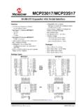
2 Packages Available temperature ranges:- Industrial (I): -40 C to +85 C- Extended (E): -40 C to +125 CDescriptionThe MCP2502X/5X devices operate as I/O expandersfor a Controller Area Network (CAN) system,supporting CAN active, with bus rates up to1 Mb/s. The MCP2502X/5X allows a simple CAN nodeto be implemented without the need for amicrocontroller. The devices are identical, with the followingexceptions:The MCP2502X/5X devices feature a number ofperipherals, including digital I/Os, four-channel 10-bitA/D (MCP2505X), and PWM outputs with automaticmessage transmission on change-of-input state.
3 Thisincludes an analog input exceeding a preset threshold. One mask and two acceptance filters are provided togive maximum flexibility during system design withrespect to identifiers that the device will respond device can also be configured to automaticallytransmit a unique message whenever any of severalerror conditions device is pre-programmed in non-volatile memoryso that the part defaults to a specific configuration Types DeviceA/DOne Wire Digital CANbusMCP25020 NoNoMCP25025 NoYesMCP25050 YesNoMCP25055 YesYesGP0/AN0GP1/AN1
4 VDDTXCAN/TXRXCAN*RXCAN/NC*GP5/VREF+1234G P4/VREF-GP6/CLKOUT1413121110GP3/AN3/PWM2 OSC1/CLKINGP2/AN2/PWM156789 OSC2 VSSGP7/RST/VPPPDIP/SOIC* One-wire option available on MCP250X5 I/O Expander FamilyNot Recommended for New DesignsUse MCP2515 or MCP25625 MCP2502X/5 XDS20001664E-page 2 2007-2017 Microchip Technology of TermsThe following terms are used throughout thisdocument:I/O Expander refers to the integrated circuit (IC)device being described ( MCP2502X/5X ).Input Message term given to messages that arereceived by the MCP2502X/5X and cause the internalregisters to be modified.
5 Once the register modificationhas been performed, the MCP2502X/5X transmits aCommand Acknowledge message to indicate that thecommand was received and Acknowledge Message term given tothe message that is automatically transmitted by theMCP2502X/5X after receiving and processing an Request Message term given to theRemote Request messages that are received by theMCP2502X/5X that subsequently generate an outputmessage (data frame) in response. Output Message term given to the message that theMCP2502X/5X sends in response to an InformationRequest Bus Message term given to the message that theMCP2502X/5X transmits after completing the Power-Onand/or Self-Configuration sequences at timed intervals,if term used to describe theprocess of transferring the contents of the EPROM memory array to the SRAM memory Bus term used to describe the condition when theMCP2502X/5X is fully-configured and ready to transmitor receive on the bus.
6 This is the only state in which theMCP2502X/5X can transmit on the Detection refers to the MCP2502X/5X s abilityto automatically transmit a message based on theoccurrence of a predefined edge on any digital Detection refers to the MCP2502X/5X sability to automatically transmit a message when apredefined analog threshold is reached. 2007-2017 Microchip Technology 3 MCP2502 OVERVIEWThis document contains device-specific information onthe MCP2502X/5X Family of CAN I/O expanders . TheCAN protocol is not discussed in depth in this docu-ment.
7 Additional information on the CAN protocol canbe found in the CAN specification, as defined by Rob-ert Bosch 1-1 is the block diagram of the MCP2502X/5 Xand Ta b l e 1 - 1 is the pinout 1-1: MCP2502X/5X BLOCK DIAGRAMTABLE 1-1:PINOUT DESCRIPTIONGPIOGP4/VREF-GP3/AN3/PWM2GP2/ AN2/PWM1GP1/AN1GP0/AN0GP5/VREF+GP6/CLKOU TGP7 RST/VPPUserTimingGenerationOSC1/CLKINOSC 2/CLKOUTCANP rotocolEngineRXCANTXCAN/A/DPWM1 PWM2 Memory*TXRXCAN* Only the MCP2505X devices have the A/D MachineandControl LogicPinNamePinNumberStandard FunctionAlternate FunctionProgrammingMode FunctionGP0/AN0 *1 Bidirectional I/O pin, TTL input bufferAnalog input channelNoneGP1/AN1 *2 Bidirectional I/O pin, TTL input bufferAnalog input channelNoneGP2/AN2/PWM2 *3 Bidirectional I/O pin.
8 TTL input bufferAnalog input/PWM outputNoneGP3/AN3/PWM3 *4 Bidirectional I/O pin, TTL input bufferAnalog input/PWM outputNoneGP4/VREF-5 Bidirectional I/O pin, TTL input bufferExternal VREF-DataGP5/VREF+6 Bidirectional I/O pin, TTL input bufferExternal VREF+ inputClockVSS7 GroundNoneGroundOSC1/CLKIN8 External oscillator inputExternal clock inputNoneOSC29 External oscillator outputNoneNoneGP6/CLKOUT10 Bidirectional I/O pin, TTL input bufferCLKOUT outputNoneGP7/RST/VPP11 Input pin, TTL input bufferExternal Reset inputVPPRXCAN12 CAN data receive inputNot connected for 1-wire operationNoneTXCAN/TXRXCAN13 CAN data transmit outputCAN TX and RX for 1-wire operation (MCP250X5)NoneVDD14 PowerNonePower* Only the MCP2505X devices have the A/D 4 2007-2017 Microchip Technology : 2007-2017 Microchip Technology 5 MCP2502 MODULEThe CAN module is a protocol controller that convertsbetween raw digital data and CAN message main functional block of the CAN module is shownin Figure 2-1 and consists of.
9 CAN protocol engine Buffers, masks and filtersThe module features include: Implementation of the CAN protocol Double-buffered receiver with two separate receive buffers One full-acceptance mask (standard and extended) Two full-acceptance filters (standard and extended) One filter for each receive buffer Three prioritized transmit buffers for transmitting predefined message types Automatic wake-up on bus traffic function Error management logic for transmit and receive error states Low-power SLEEP modeFIGURE 2-1:CAN MODULERXB0 Acceptance FilterRXF1 RXB1 IdentifierData FieldData FieldIdentifierMABA cceptance MaskRXMA cceptance FilterRXF0 TXREQTXB2 ABTFMLOATXERRMESSAGEM essageQueueControlTransmit Byte SequencerTXREQTXB0 ABTFMLOATXERRMESSAGECRC<14:0>ComparatorReceive<7:0>Transmit<7:0>ReceiveErrorTransmitErrorProtocolRECTECE rrPasBusOffFiniteStateMachineCounterCoun terShift<14:0>{Transmit<5:0>, Receive<8.}
10 0>}TransmitLogicBitTimingLogicTXCAN/TXRX CANRXCANC onfigurationRegistersClockGeneratorPROTO COLENGINEBUFFERSTXREQTXB1 ABTFMLOATXERRMESSAGEACCEPTACCEPTMCP2502X /5 XDS20001664E-page 6 2007-2017 Microchip Technology Protocol Finite State MachineThe heart of the engine is the Finite State Machine(FSM). This state machine sequences through mes-sages on a bit-by-bit basis, changing states as thefields of the various frame types are transmitted orreceived. The FSM is a sequencer controlling thesequential data stream between the TX/RX Shiftregister, the CRC register and the bus line.