Transcription of Meeting Transient Specifications for Electrical …
1 AN:214 Page 1 Meeting Transient Specificationsfor Electrical Systems in Military VehiclesIntroductionElectrical systems in military vehicles are normally required to meet stringent Transient requirements. Typical of these Specifications is the MIL-STD-1275B. Although the specified levels of these surges and spikes are outside the capability of Vicors Maxi, Mini, Micro Series modules, it is quite possible, with simple circuitry, to make the 24V input (18 36V input range) DC-DC converter modules compliant to these Specifications for the 28V vehicle voltage system . Other electro-magnetic compatibility requirements, such as MIL-STD-461E and/or DEF-STAN 59-41, apply to military vehicles, but these are outside the scope of this application note. In order to meet additional conducted emission requirements an input filter, preceding the Transient protection circuit covered in this application note, will be transients on this 28V rail fall into two types: 1.
2 Spikes: typically high voltage rise, short duration and low Surges: typically lower voltages rise, long duration and high systems are battery plus generator fed with spike and surge requirements that can be easily met using the M-FIAM5 filter and Transient protection module. The level of immunity imposed by MIL-STD-1275 requires additional protection such as that presented here. Incidentally, both surges and spikes are most onerous in generator-only systems. Table 1 summarizes the worst-case spike and surge requirements for the two -1275 BDEF-STAN 61-5 SpikesAmplitude 250V 50 s spike width in a burst up to 1ms duration with 15mJ maximum energy content per spikeAmplitude +270V & -220V 10 s max. Plus +110V train of spikes lasting up to 5msSurges100V for 50ms from a source impedance, repeated 5 times once per second100V (+5/-0%) for 50ms from a source impedance, repeated 5 times once per second (Annex C)Note: Low line dips to 15V specified in the above Specifications are likely to result in the DC-DC converter module turning off during this period.
3 Cranking voltages will also activate the undervoltage lock protect the power converter module from these transients, two separate techniques must be used. For spikes, a parallel Transient filter, , input TransZorbs , can easily remove these low energy high voltage bursts. Three P6KE33A should be placed in series and connected across the input rail, but a single could be an adequate alternative for spike removal. For surges, because of their duration and energy, the only feasible removal method is a series surge suppression circuit, , a properly controlled power semiconductor(s) is/are placed in series with the input line. Since the 24V modules have a maximum input voltage of 36V, the ideal surge protection circuit would allow current to be supplied to the load module,while dropping the excess voltage associated with a surge event. The series pass element must dissipate the power associated with the excess voltage and load current.
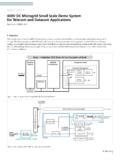
4 Large loads require significant power handling capability. The most suitable device for this application is a MOSFET. A BJT could also be used, but during normal operation a 1V drop across this device would have to be NOTE | AN:214 Arthur Jordan Senior Applications EngineerContents PageTable 1 Worst-case Transient RequirementsIntroduction 1 Circuit Description and Operation 2 Low Line Operation 3 Filtering Higher Power Modules 3 Appendix and Notes 4 MOSFET Safe Operating Area (SOA) 5 Expanding Power Handling 6 Waveforms & Data 6 References 11 AN:214 Page 2 Circuit Description and OperationFigure 1 is a diagram of a Transient /surge protection circuit. High voltage, low energy spikes are absorbed by the capacitor and TransZorb s across the input.
5 All of the remaining circuitry addresses the problem of high energy surges by performing two functions. (1) The output is clamped at 35V in the event that the input rises beyond that point. (2) If the overvoltage condition at the input persists for a period greater than 55ms, the converter is shut down via the PC charge pump provides full enhancement gate bias to the MOSFET (Q1) during normal operation. This function is accomplished by U1, an ICM7555 timer, which generates a rectangular waveform at 109kHz, that is peak detected and level shifted by R3, C4, D1 & D3. Capacitor C7 limits the rate of rise of the voltage across the output to 160 170V/ms, which in turn, limits the inrush current at start up to with a 1000 F (C5) capacitor across the output. The V24 series of modules employ undervoltage lockout at approximately 16V, and a soft start feature.
6 Start up takes longer than 10ms after crossing the lockout threshold. Zener diode D5 limits the maximum voltage that can be applied to the gate of the Transient protection MOSFET to 15V, with respect to its source. If the input voltage exceeds , this circuit performs as a series pass linear regulator. The output voltage is compared with the LM10 s reference voltage ( ). The error signal at the output of the LM10 is used to control transistor Q2 (2N5550), causing FET Q1 (IXTH75N10) to act as a voltage regulator. Capacitor C6 is the main spike removal device (the TransZorbs are only for added protection). C6 can also help reduce any high frequency ringing that may be applied to the circuit, although a small damping resistor in series with this capacitor may be required if the TransZorbs are not to be relied upon. D4 is added to limit the maximum voltage on C7, at high line, that may slow down the response time of this circuit.
7 Usually, this protection circuit should be placed after the system s EMI filter, because a differential source inductance of at least 10 H is recommended to ensure that Q1 is not over stressed during high slew rate inductance in excess of this value is also required to meet military EMI requirements. The value of C5 is dependent on the module and the application, but it must not exceed 1000 F for this circuit. Normally, 330 F is a large enough input capacitor for a single the circuit of Figure 1 power handling is limited by FET Q1, particularly during the brief explanation of the theoretical handling capability of this MOSFET is given in the appendix. In short, this MOSFET, provided its case temperature is kept below 70 C, will provide protection for a 125W load (a single V24 100W micro module, fully loaded) during a 100V surge lasting 50ms. A simple additional circuit, shown in Figure 2, can provide extra system protection in the event of a sustained overvoltage condition.
8 If a surge lasts longer than about 50 60ms, or repeats faster than once per second, this circuit will turn off the attached module. Because the power dissipated in the MOSFET is proportional to loading of the Transient protection circuit, it will withstand 100V surges, in the unloaded condition, almost indefinitely. This additional protection should be employed in most R61N41481N4148D1U6220nF2N5550D41N4755C7Q 2R1568 10 F100 R4R51k +C3C41nFU1UA555R368 R2U4U5D21000 F + R14R1356k FC21nfR9100k R1010k R12300 U2LM10C+ 3241687 Figure 1 Transient Protection Filter Circuit AN:214 Page 3To 'PC'To '-IN' Transient Filter InputGroundQ3BC107 BPD9 BZX84C36LT1+C9470 FU6U7U5R8910 R711k U3 Figure 2 Surge Duration Protection CircuitLow Line OperationFor the circuit of Figure 1 used at the suggested power, therewill be approximately 120mV drop due to the ON resistanceof the MOSFET.
9 Some further allowance should also be made for the EMI filter and trace resistances. Therefore, low line performance can be improved by using larger or paralleled MOSFETs. Although the maximum undervoltage turn on voltage for V24 range of modules is , they will in most instances operate (with some derating) down to 16V input, once started. Please note that many applications do not require operation during cranking but must operate down to minimum (including ripple) for Higher Power ModulesTo provide Transient protection for higher power modules, , Mini and Maxi modules, either MOSFETs with larger Safe Operating Areas (SOAs), or arrays of MOSFETs must be used. Presently, there is limited availability of dies of the required size to achieve the low thermal impedance required. However,many manufacturers make packaged arrays of MOSFETs for higher power applications such as the IRFK6J150 (six MOSFETs in parallel in this TO-240 package) that have a sufficiently large SOA to provide protection for a single Mini module (fully loaded) provided this HEX-pak case temperature does not exceed 57 C before the application of the surge.
10 However, since distributors and suppliers often do not stock these parts, a custom array of MOSFETs is often the only recourse. MOSFETs will share current adequately during a surge event if the following conditions are All the MOSFETs in the array are of the same type and ideally from the same production All the MOSFETs in the array are thermally coupled to the same heat sink, ( , all the MOSFETs need to have the same device temperature).c. All the MOSFETs in the array have their own gate resistor, ( , each MOSFET must have its own 22-10 0 , R4 resistor).d. Drain, gate and source, current traces should be of similar lengths and A small source resistor R6 can be added for improved MOSFET current sharing, if discussion of the reasoning behind these criteria is given in the Appendix & Notes section. Under the above ideal circumstances, sharing should be very accurate; however, because points (a) and (b) are unlikely to be always met, some degree of derating is advisable.