Transcription of MEMS digital output motion sensor: ultra-low …
1 This is information on a product in full production. December 2015 DocID025344 Rev 51/47 LIS2HH12 MEMS digital output motion sensor: ultra-low -power high-performance 3-axis "pico" accelerometerDatasheet - production dataFeatures Wide supply voltage, V to V Independent IOs supply ( V) and supply voltage compatible ultra-low power consumption 2g/ 4g/ 8g full-scale I2C/SPI digital output interface 16-bit data output Embedded temperature sensor Embedded self-test Embedded FIFO 10000 g high shock survivability ECOPACK , RoHS and Green compliantApplications motion -controlled user interfaces Gaming and virtual reality Pedometers Intelligent power saving for handheld devices Display orientation Click/double-click recognition Impact recognition and logging Vibration monitoring and compensationDescription The LIS2HH12 is an ultra-low -power high-performance three-axis linear accelerometer belonging to the pico LIS2HH12 has full scales of 2g/ 4g/ 8g and is capable of measuring accelerations with output data rates from 10 Hz to 800 self-test capability allows the user to check the functioning of the sensor in the final LIS2HH12 has an integrated first-in, first-out (FIFO) buffer allowing the user to store data in order to limit intervention by the host processor.
2 The LIS2HH12 is available in a small thin plastic land grid array package (LGA) and it is guaranteed to operate over an extended temperature range from -40 C to +85 C LGA-12 ( mm) Table 1. Device summaryOrder codesTemperature range [ C]Package PackagingLIS2HH12-40 to +85 LGA-12 TrayLIS2HH12TR-40 to +85 LGA-12 Tape and Rev 5 Contents1 Block diagram and pin description .. diagram .. description .. 82 Mechanical and electrical specifications .. characteristics .. characteristics .. sensor characteristics .. interface characteristics .. - serial peripheral interface .. - inter-IC control interface .. maximum ratings .. and functionality .. level .. element .. interface .. 163 Factory calibration .. 164 Application hints .. information .. 175 digital main blocks .. function.
3 Stabilization time / ODR change .. mode .. mode .. mode .. mode .. mode .. 21 DocID025344 Rev 53 mode .. data from FIFO .. multiple reads (burst) .. 226 digital interfaces .. serial interface .. operation .. bus interface .. read .. write .. read in 3-wire mode .. 287 Register mapping .. 298 Register description .. (0Bh), TEMP_H (0Ch) .. (0Fh) .. (1Eh) .. (1Fh) .. (20h) .. (21h) .. (22h) .. (23h) .. (24h) .. (25h) .. (26h) .. (27h) .. (28h) - OUT_X_H (29h) .. (2Ah) - OUT_Y_H (2Bh) .. (2Ch) - OUT_Z_H (2Dh) .. (2Eh) .. (2Fh) .. (30h) .. (31h) .. (32h), IG_THS_Y1 (33h), IG_THS_Z1 (34h) .. 40 ContentsLIS2HH124/47 DocID025344 Rev (35h) .. (36h) .. (37h) .. (38h) .. (39h) .. (3Ah), XH_REFERENCE (3Bh).
4 (3Ch), YH_REFERENCE (3Dh) .. (3Eh), ZH_REFERENCE (3Fh) .. 429 Package information .. package information .. packing information .. 4410 Revision history .. 46 DocID025344 Rev 55/47 LIS2HH12 List of tables47 List of tablesTable summary .. 1 Table description .. 9 Table characteristics @ Vdd = V, T = 25 C unless otherwise noted .. 10 Table characteristics @ Vdd = V, T = 25 C unless otherwise noted .. 11 Table sensor characteristics .. 11 Table slave timing values.. 12 Table slave timing values .. 13 Table maximum ratings .. 14 Table function control registers ..18 Table of samples to be discarded .. 19 Table interface pin description .. 23 Table terminology ..23 Table +Read/Write patterns .. 24 Table when master is writing one byte to slave .. 24 Table when master is writing multiple bytes to slave.
5 25 Table when master is receiving (reading) one byte of data from slave .. 25 Table when master is receiving (reading) multiple bytes of data from slave .. 25 Table map.. 29 Table register default values.. 31 Table register default values ..31 Table register default values..31 Table register 1 .. 31 Table register 1 description .. 31 Table register setting .. 32 Table cutoff frequency in high resolution mode (HR = 1) .. 32 Table register 2 .. 33 Table register 2 description .. 33 Table register 3 .. 34 Table register 3 description .. 34 Table register 4 .. 34 Table register 4 description .. 34 Table register 5 .. 35 Table register 5 description .. 35 Table mode selection .. 35 Table register 6 .. 36 Table register 6 description .. 36 Table register 7 .. 36 Table register 7 description.
6 36 Table register .. 37 Table register description .. 37 Table control register .. 38 Table control register description.. 38 Table mode selection.. 38 Table status register .. 38 Table status register description .. 38 Table configuration register ..39 Table configuration register description .. 39 Table register .. 39 List of tablesLIS2HH126/47 DocID025344 Rev 5 Table register description ..39 Table register .. 40 Table description.. 40 Table duration .. 40 Table duration description ..40 Table register .. 40 Table register description .. 40 Table register .. 41 Table register description .. 41 Table register .. 41 Table register description .. 41 Table register .. 41 Table register description .. 41 Table 2x2x1 package mechanical data .. 43 Table dimensions for carrier tape of LGA-12 package.
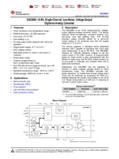
7 45 Table revision history.. 46 DocID025344 Rev 57/47 LIS2HH12 List of figures47 List of figuresFigure diagram .. 8 Figure connections .. 8 Figure slave timing diagram .. 12 Figure slave timing diagram.. 13 Figure electrical connections ..17 Figure mode .. 20 Figure multiple reads .. 22 Figure and write protocol .. 25 Figure read protocol .. 26 Figure byte SPI read protocol (2-byte example) .. 27 Figure write protocol .. 27 Figure byte SPI write protocol (2-byte example).. 27 Figure read protocol in 3-wire mode .. 28 Figure 2x2x1 package outline..43 Figure tape information for LGA-12 package .. 44 Figure package orientation in carrier tape .. 44 Figure information for carrier tape of LGA-12 package .. 45 Block diagram and pin descriptionLIS2HH128/47 DocID025344 Rev 51 Block diagram and pin Block diagramFigure 1.
8 Block Pin descriptionFigure 2. Pin connectionsCHARGEAMPLIFIERY+Z+Y-Z-aX+X-I 2 CSPICSSCL/SPCSDA/SDI/SDOSDO/SA0 INT1 CLOCKTRIMMINGCIRCUITSREFERENCESELF TESTA/DCONVERTER1 INT2 MUXCONTROLLOGICTEMP. SENSORFIFOA/DCONVERTER2(TOP VIEW)DIRECTION OF THEDETECTABLEACCELERATIONSX1 YZVdd_IOSCL/SPCSDA/SDI/SDOCSSDO/SA0 RESGNDINT1 INT2 RESVddRES(BOTTOM VIEW)Pin 1 indicator4157118 RESRES1214 GNDSCL/SPCSDA/SDI/SDOCSSDO/SA0 GNDRESINT 1 Vdd_IO(BOTTOM VIEW)4156 GND11 INT 2710 Vdd12 DocID025344 Rev 59/47 LIS2HH12 Block diagram and pin description47 Table 2. Pin description Pin#NameFunction1 SCLSPCI2C serial clock (SCL)SPI serial port clock (SPC)2 CSSPI enableI2C/SPI mode selection (1: SPI idle mode / I2C communicationenabled; 0: SPI communication mode / I2C disabled)3 SDOSA0 SPI serial data output (SDO)I2C less significant bit of the device address (SA0)4 SDASDISDOI2C serial data (SDA)SPI serial data input (SDI)3-wire interface serial data output (SDO)5 RESC onnect to GND6 GND0 V supply7 GND0 V supply8 GND0 V supply9 VddPower supply10 Vdd_IOPower supply for I/O pins11 INT2 Interrupt pin 2 12 INT1 Interrupt pin 1 Mechanical and electrical specificationsLIS2HH1210/47 DocID025344 Rev 52 Mechanical and electrical Mechanical characteristicsTable 3.
9 Mechanical characteristics @ Vdd = V, T = 25 C unless otherwise noted (1)SymbolParameterTest (2) range(3) @ FS g @ FS g @ FS g change vs. CTyOffTypical zero-g level offset accuracy(4) 30mgTCOffZero-g level change vs. temperature(4)Delta from 25 C CTonTurn-on timeNumber of samples to be discarded from power-down to active modeCTRL4 (23h) (BW_SCALE_ODR) = 01# of samplesSTSelf-test positive difference(5) 701500mgTo pOperating temperature range-40 +85 C1. The product is factory calibrated at V. The operational power supply range is from V to V. 2. Typical specifications are not Verified by wafer level test and measurement of initial offset and Offset can be eliminated by enabling the built-in high-pass Self-test positive difference is defined as: output [mg](CTRL5 ST2, ST1 bits=01) - output [mg](CTRL5 ST2, ST1 bits=00).
10 DocID025344 Rev 511/47 LIS2HH12 Mechanical and electrical Electrical Temperature sensor characteristics@ Vdd = V, T=25 C unless otherwise notedTable 4. Electrical characteristics @ Vdd = V, T = 25 C unless otherwise noted (1) SymbolParameterTest (2) pins supply voltage(3) + consumptionin active modeODR 100-800 Hz180 AODR 50 Hz110 AODR 10 Hz50 AIddPdnCurrent consumption inpower-down mode5 AVIHD igital high-level input *Vdd_IOVVILD igital low-level input *Vdd_IOVT bootBoot time(4)20msTopOperating temperature range-40+85 C1. The product is factory calibrated at V. The operational power supply range is from V to Typical specifications are not It is possible to remove Vdd maintaining Vdd_IO without blocking the communication busses, in this condition the measurement chain is powered Time to complete the entire boot sequence: from Vdd on until all configuration and calibration parameters are correctly loaded into device 5.