Transcription of MFX Single output DC-DC Converters - Interpoint
1 DeSCriptionThe Interpoint MFX Series of high efficiency DC-DC Converters offers a wide input voltage range of 16 to 50 volts and up to 50 watts of output power. The MFX Converters are manufactured in our fully certified and qualified MIL-PRF-38534 Class H production facility and packaged in hermetically sealed steel cases. They are ideal for use in programs requiring high reliability, small size, and high efficiency. These Converters are capable of withstanding short term transients up to 80 volts per MIL-STD-704A. Flanged and non-flanged models are dESignThe MFX Converters are switching regulators that use an active-clamp reset, Single -ended forward converter and synchronous rectification design with a constant switching frequency of 500 kHz, typical.
2 Isolation between input and output circuits is provided with transformers in the power path and in the feedback control loop. The converter design is further described in sections Operation and control on page PowEr dEnSityThe MFX Series offers a new standard of performance for small size and high power density. At just inches ( mm) high and a total footprint of in2 (15 cm2), this low profile package offers a total power density of approximately 50 watts per cubic noiSEThe MFX Converters current mode control system provides excellent dynamic response and audio rejection. See Figure 12 on page MFX Series Converters implement an internal input filtering to reduce emissions to a level acceptable for many applications.
3 For applications required to meet MIL-STD-461C CE03 and/or MIL-STD-461D, E and F CE102 levels of conducted emission consider the Interpoint FMCE family of EMI functionMFX Converters provide an inhibit terminal that can be used to disable internal switching, resulting in no output and very low quiescent input current. The converter is inhibited when the inhibit pin is pulled to volts or less. The unit is enabled when the pin, which is internally connected to a pull-up current source, is left unconnected or is connected to an open-collector. The open circuit voltage associated with the inhibit pin is 14 to 18 volts. The inhibit pin may sink up to 4 mA maximum when driven to an active low condition.
4 See Table 5 on page 9 for more circuit ProtEctionMFX Series Converters provide short circuit protection by restricting the output current to approximately 130% of the full load output current. See output Overload and Short Circuit Protection for more details. undErVoltagE lockoutUndervoltage lockout with hysteresis prevents the units from operating below approximately 15 volts input voltage to keep system current levels smooth, especially during initialization or re-start 89 to 93% typical efficiency Wide input range, 16 to 50 volts 10% trimmable outputs Transient protection up to 80 volts per MIL-STD-704A Fully isolated, magnetic feedback -55 C to +125 C operation Undervoltage lockout Inhibit functionMoDelSouTpuT VolTage (V) Crane Aerospace & Electronics Power SolutionsMFX Single output DC-DC ConvertersCrane Aerospace & ElectronicsPower Solutions Interpoint Products10301 Willows Rd.
5 NE, Redmond, WA 98052+1 1 of 1816 to 50 VoltS input - 50 WattMFX Rev AG - normal operation, the output capacitors are charged at the regulated output voltage and can be used for holdup purposes. When the MFX converter is turned off either through removal of the input line voltage or assertion of inhibit, the synchronous rectifiers will continue to switch until the total energy stored in the internal and external output capacitors is safely depleted. Due to this behavior the energy in the output capacitor will be discharged and may not be suitable for holdup of ExtErnal VoltagE SourcE and PrE-BiaS StartuPDo not apply an external voltage source across the MFX converter output as it may turn on the self driven synchronous rectification (SDSR) causing the converter to sink current from the source.
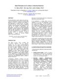
6 The MFX Converters do not support pre-biased startup applications. The converter will sink current from the load and may not startup if an external bias is present on the output of the converteroutPut and rEmotE SEnSE connEctionSCare must be taken to avoid accidental disconnection of the Positive output (Pins 5, 6) or output Common (Pins 3, 4) when Remote Sense is used. If the sense pins are connected to the load, but the output power pins are not connected to the load, then the converter may be currEnt SharingThe MFX Converters do not support load current sharing or parallel operation. The Converters can be damaged if their outputs are directly connected per Figure 2. StackingMFX Converters do not support stacking voltages.
7 (See following pages for Redundancy , Inhibit and output Overload and Short Circuit Protection )PositiveOutputOutputCommonLoad+ +3, 45, 6 PositiveOutputOutputCommon +3, 45, 6 This connection candamage the The MFX is a Single -ended, active clamp, forward DC-DC converter . The active-clamp reset technique offers several advantages for wide input voltage range compared to other passive reset methods. It reduces switching losses and lowers the voltage stress on the power switch. The efficiency can then be improved by selecting MOSFETs with lower voltage rating which provides lower on-state is typically performed using ultrafast diodes or Schottky diodes. The conduction loss on such rectifiers can become a significant portion of the total power loss for low-voltage output and high-power applications.
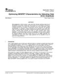
8 To maximize the benefits of active-clamp reset the MFX is designed with self-driven synchronous rectifiers (SDSR) to reduce the conduction losses. The MFX employs a unique synchronous gate-drive circuitry that automatically adjusts for the wide input voltage operating conditions when the PWM is not switching the MFX can sink current from an external voltage source applied to its output . This behavior is inherent to the SDSR in the MFX. To prevent damage to the Converters , do not use them with pre-bias startup, load current sharing or parallel operation. These characteristics are discussed in the control on page 2 DriveGate Drive+-+VO-VOCOLOV prebiasRloadExternal SourcesMFXfigurE 1: PrE-BiaS StartuP iS not SuPPortEdfigurE 2: thE mfx Converters can BE damagEd if connEctEd togEthEr for load currEnt Sharing Crane Aerospace & Electronics Power SolutionsMFX Single output DC-DC Converters28 Volt input 25 2 of 18 MFX Rev AG - to 50 VoltS input - 50 WattrEdundancyIn redundant systems, multiple Converters are used in parallel to provide uninterrupted power and to improve reliability.
9 This can be implemented by connecting ORing diodes on the output of each converter per Figure 3. The diode provides isolation of the converter from the load and other Converters in the event of a failure. The ORing diodes also provide redundancy in the event that a converter turns off earlier or turns on later than the others. When the MFX is used with ORing diodes, the remote sense connections on the MFX Converters must be connected locally to the individual converter s output and cannot be connected to the cathode of the ORing diodes. Redundancy can instead be achieved with active ORing using power MOSFETs and controller IC, which can to reduce thermal dissipation and improve system efficiency.
10 The MFX Converters cannot be used with MOSFETs for ORing purposes unless only one device is active at any given time. This requires an ORing MOSFET controller that can selectively disable all ORing MOSFETs except for one operational MFX converter can be inhibited by pulling the inhibit pin low using an open-collector connection. The inhibit pin is internally connected to a pull-up with a typical open-pin voltage of 16V. Following a shutdown event by assertion of the inhibit function the assert to de-assert delay time must be at least 10 ms for no capacitive loading and 150 ms for maximum capacitive loading. The inhibit signal to the inhibit pin must also use debounce circuitry to prevent rapid turn-off and turn-on as this may cause damage to the converter .