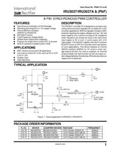
Transcription of MIC2128 75V, Synchronous Buck Controller …
1 2017 Microchip Technology 1 MIC2128 Features Hyper Speed control Architecture Enables:- High Input to Output Voltage Conversion Ratio Capability- Any Capacitor Stable- Ultra-Fast Load Transient Response Wide to 75V Input Voltage Range Adjustable Output Voltage from to 30V 270 kHz to 800 kHz Programmable Switching Frequency Built-in 5V Regulator for Single-Supply Operation Auxiliary Bootstrap LDO for Improving System Efficiency Internal Bootstrap Diode Adjustable Soft-Start Time Enable Input and Power Good Output Programmable Current Limit Hiccup Mode Short-Circuit Protection Internal Compensation and Thermal Shutdown Supports Safe Start-Up into a Prebiased Output Applications Networking/Telecom Equipment Base Station.
2 Servers Distributed Power Systems Industrial Power SuppliesGeneral DescriptionThe MIC2128 is a constant-frequency synchronousbuck Controller featuring a unique adaptive on-timecontrol architecture with external soft start. TheMIC2128 operates over an input voltage range to output voltage is adjustable down with a guaranteed accuracy of 1%. The deviceoperates with programmable switching frequency from270 kHz to 800 kHz. The MIC2128 features an external soft-start pin (SS)which allows the user to adjust output soft-start time toreduce inrush current from mains during start-up. TheMIC2128 features an auxiliary bootstrap LDO whichimproves the system efficiency by supplying theMIC2128 internal circuit bias power and gate driversfrom output of the converter.
3 A logic level enable (EN)signal can be used to enable or disable MIC2128 can start-up monotonically intoa prebiased output. The MIC2128 features an opendrain power good signal (PG) which signals when theoutput is in regulation and can be used for simplepower supply sequencing purpose. The MIC2128 offers a full suite of protection features toensure protection of the IC during Fault include undervoltage lockout to ensure properoperation under power-sag conditions, hiccup modeshort-circuit protection and thermal shutdown. The MIC2128 is available in a 16-pin 3 mm x 3 mmQFN package, with an operating junction temperaturerange from -40 C to +125 Types2 SWBSTPGSSFREQDHENPGNDDLPVDDEXTVDDVINVDDA GNDFBILIM16115 14133411109567812 MIC21283x3 QFN*(Top View) EP* Includes Exposed Thermal Pad (EP).
4 See Table , Synchronous buck Controller Featuring Adaptive On-Time control with External Soft StartMIC2128DS20005620B-page 2 2017 Microchip Technology ApplicationFunctional Block to FX347 F10 nF1 ё 18 kё kё 1 kё 100 kё 60 kё kё VINMIC2128 PGNDAGNDDHDL10 nF330 F+ FQ1Q2Q1,Q2: SiR878 ADPL1: SRP1265A-100M, BournsC1: 10 SVP330ML1C1 SWPGVDDBSTPVDDFREQPVDDVINPGNDILIMN egative Current Limit815 THERMALSHUTDOWN11 TONESTIMATIONC ontrolLogic141 AGNDEN1029 EXTVDDLINEARREGULATORgm13 FBCOMPENSATIONVREFFB5DH7DL12SS3416 CURRENT A6 2017 Microchip Technology CHARACTERISTICSA bsolute Maximum Ratings VIN, FREQ, ILIM, SW to to +76 VVDD, PVDD, FB, PG, SS to to +6 VEXTVDD to to +16 VBST to SW.
5 To +6 VBST to AGND .. to +82 VEN to to (VIN + )DH, DL to to (VDD + )PGND to to + Temperature .. +150 CStorage Temperature (TS) .. -65 C to +150 CLead Temperature (soldering, 10s) .. 260 CESD Rating(1).. 1000 VNote 1:Devices are ESD sensitive. Handling precautions recommended. Human body model, k in series with100 Ratings(1)Supply Voltage (VIN) .. to 75 VSW, FREQ, ILIM, 0V to VINJ unction Temperature (TJ) .. -40 C to +125 CPackage Thermal Resistance (3 mm 3 mm QFN-16)Junction to Ambient ( JA) .. C/WJunction to Case ( JC).. C/WNote 1:The device is not ensured to function outside the operating range. Notice: Stresses above those listed under Maximum Ratings may cause permanent damage to the device.
6 This isa stress rating only and functional operation of the device at those or any other conditions above those indicated in theoperational sections of this specification is not intended. Exposure to maximum rating conditions for extended periodsmay affect device 4 2017 Microchip Technology CHARACTERISTICS (Note 1)Electrical Specifications: unless otherwise specified, VIN= 12V, VOUT= ; VBST-VSW=5V, TA=+25 C. Boldface values indicate -40 C TJ +125 C (Note 2). ConditionsPower Supply InputInput Voltage Range and VDD shorted to VIN (VPVDD=VVIN=VVDD) 75 Quiescent Supply CurrentIQ , no switchingShutdown Supply CurrentIVIN(SHDN) AEN = Low 3060 AEN = Low, VIN=VDD= ,VDD and EXTVDDPVDD Output 7V to 75V, IPVDD=10mAVDD UVLO risingVDD UVLO HysteresisVVDD_UVLO_Hys 600 mVVDD fallingEXTVDD Bypass risingEXTVDD Bypass Hysteresis VEXTVDD_Hys 200 mVEXTVDD Dropout Voltage 250 mVVEXTVDD=5V, IPVDD=25mAReferenceFeedback Reference TJ= 25 C -40 C TJ 125 C FB Bias CurrentIFB 50500nAVFB = ControlEN Logic Level VEN Logic Level LowVEN_L HysteresisVEN_Hys 150 mVEN Bias CurrentIEN 630 AVEN=12 VON TimerSwitching Frequency f0 800 kHzVFREQ=VVIN, VVIN=12V230270300 VFREQ= 33% of VVIN, VVIN=12 VMaximum Duty CycleDMAX 85 %VFREQ=VVIN = 12 VMinimum Duty Cycle DMIN 0 %VFB > ON TimetON(MIN) 80 nsMinimum OFF TimetOFF(MIN)
7 150230350nsSoft-StartSoft-Start Current SourceISS ACurrent Limit Current-Limit Comparator OffsetVOFFSET -15015mVVFB = Source CurrentICL8096110 AVFB = Source Current Tempco A/ CNegative Current Limit Comparator Threshold 48 mVNote 1:Specification for packaged product :The application is fully functional at low VDD (supply of the control section) if the external MOSFETs have low voltage VTH. 2017 Microchip Technology 5 MIC2128 FET DriversDH On-Resistance, High StateRDH(PULL-UP) 23 DH On-Resistance, Low StateRDH(PULL_DOWN) 24 DL On-Resistance, High StateRDL(PULL-UP) 24 DL On-Resistance, Low State RDL(PULL_DOWN) SW, VIN and BST LeakageBST Leakage 30 AVIN Leakage 50 ASW Leakage 50 APower Good (PG)PG Threshold VoltageVPG_Rise85 95%VOUTVFB risingPG HysteresisVPG_Hys 6 %VOUTVFB fallingPG Delay TimePG_R_DLY 100 sVFB risingPG Low VoltageVOL_PG 70200mVVFB < 90% VNOM, IPG=1mAThermal ProtectionOvertemperature ShutdownTSHDN 150 CJunction temperature risingOvertemperature Shutdown HysteresisTSHDN_Hys 15 CELECTRICAL CHARACTERISTICS (Note 1)Electrical Specifications.
8 Unless otherwise specified, VIN= 12V, VOUT= ; VBST-VSW=5V, TA=+25 C. Boldface values indicate -40 C TJ +125 C (Note 2). ConditionsNote 1:Specification for packaged product :The application is fully functional at low VDD (supply of the control section) if the external MOSFETs have low voltage 6 2017 Microchip Technology CHARACTERISTIC CURVESNote: Unless otherwise indicated, VVIN=12V, fSW=300kHz, RILIM= , L = 10 H, VEXTVDD=VOUT, TA=+25 C(refer to the Typical Application circuit).FIGURE 2-1:Input Supply Current vs. Input 2-2:Input Supply Current vs. 2-3:Input Shutdown Current vs. Input 2-4:Input Shutdown Current vs. 2-5:PVDD Line RegulationFIGURE 2-6:PVDD Voltage vs. :The graphs and tables provided following this note are a statistical summary based on a limited number ofsamples and are provided for informational purposes only.
9 The performance characteristics listed hereinare not tested or guaranteed. In some graphs or tables, the data presented may be outside the specifiedoperating range ( , outside specified power supply range) and therefore outside the warranted 121824303642485460667278 Input Supply Current (mA)Input Voltage (V)VOUT= 5 VIOUT= 0 AFSW= 300 kHzVEN= VVIN051015202530-50-250255075100 Input Supply Current (mA)Temperature ( C)VVIN= 48 VIOUT= 0 AFSW= 300 kHzVEN= VINVEXTVDD= VOUTEXTVDD = GND01002003004005006006 183042546678 Input Current ( A)Input Voltage (V)VVIN= 48V, with resistor divider between VINand AGNDat FREQ pin (100 k and 60 k )EN = GND250260270280290300310320330340350-50- 25 0 255075100 Input Current ( A)Temperature ( C)
10 VVIN= 48V, with resistor divider between VINand AGNDat FREQ pin (100 k and 60 k )EN = 121824303642485460667278 PVDD Voltage (V)Input Voltage (V)IPVDD= 10 mAVEN= VVINEXTVDD = GND 0 255075100 PVDD Voltage (V)Temperature ( C)VVIN= 48 VIPVDD= 10 mAVEN= VVINEXTVDD = GNDVEXTVDD= 12 VVEXTVDD= 12 VVEXTVDD= 5 VVEXTVDD= 12V 2017 Microchip Technology 7 MIC2128 Note: Unless otherwise indicated, VVIN=12V, fSW=300kHz, RILIM= , L = 10 H, VEXTVDD=VOUT, TA=+25 C(refer to the Typical Application circuit).FIGURE 2-7:PVDD Load 2-8:VDD UVLO Threshold vs. 2-9:EXTVDD Threshold vs. 2-10:Enable Threshold vs. 2-11:Enable Bias Current vs. TemperatureFIGURE 2-12:Switching Frequency vs. Input 102030405060 PVDD Voltage (V)IPVDD(mA)VVIN= 48 VVEN= VVINVEXTVDD= 5 VEXTVDD = GNDVEXTVDD= Voltage (V)Temperature ( C)IVDD= 0 mAEXTVDD = Voltage (V)Temperature ( C) Voltage (V)Temperature ( C) Current ( A)Temperature ( C)VVIN= 12 VVEN= 5V2202302402502602702802903003103206 121824303642485460667278 Switching frequency (kHz)Input Voltage (V)VOUT= 5 VFSW_SETPOINT= 300 kHzVEXTVDD= VOUTVEN= VVINIOUT=0 AIOUT= 5 AMIC2128DS20005620B-page 8 2017 Microchip Technology : Unless otherwise indicated, VVIN=12V, fSW=300kHz, RILIM= , L = 10 H, VEXTVDD=VOUT, TA=+25 C(refer to the Typical Application circuit).