Transcription of MoCA 2.0 Specification for Device RF Characteristics …
1 Copyright 2015 MoCA Alliance Page 1 of 34 MoCA Specification for Device RF Characteristics 20150406 Copyright 2012, 2014 Multimedia Over Coax Alliance. All Rights Reserved. MoCA is a trademark or registered trademark of the Multimedia Over Coax Alliance in the United States and other countries. Copyright 2015 MoCA Alliance Page 2 of 34 IMPORTANT NOTICE. THIS DOCUMENT AND THE INFORMATION CONTAINED HEREIN ARE PROVIDED "AS IS" AND WITH ALL FAULTS . NEITHER MOCA NOR ANY MEMBER OF MOCA MAKES ANY REPRESENTATIONS OR WARRANTIES OF ANY KIND WHATSOEVER WITH RESPECT TO (A) THIS DOCUMENT, (B) ANY PRODUCT THAT IS DEVELOPED OR MANUFACTURED IN ACCORDANCE WITH THE SPECIFICATIONS IN THIS DOCUMENT OR (C) THE INTEROPERABILITY OF ANY SUCH PRODUCT WITH ANY OTHER PRODUCT.
2 MOCA AND MOCA MEMBERS DISCLAIM ALL IMPLIED WARRANTIES, INCLUDING WITHOUT LIMITATION THE IMPLIED WARRANTIES OF MERCHANTABILITY, FITNESS FOR A PARTICULAR PURPOSE, ACCURACY, NON-INFRINGEMENT AND TITLE. NEITHER MOCA NOR ANY MEMBER OF MOCA MAKES ANY REPRESENTATIONS OR WARRANTIES THAT THE CONTENTS OF THE DOCUMENT ARE COMPLETE, ACCURATE OR SUITABLE FOR ANY PURPOSE OR THAT ANY PRODUCT OR OTHER IMPLEMENTATION OF SUCH CONTENTS WILL NOT INFRINGE ANY PATENTS, COPYRIGHTS OR OTHER RIGHTS. IN NO EVENT WILL MOCA OR ANY MOCA MEMBER BE LIABLE FOR ANY LOSSES, INVESTMENTS MADE, LIABILITIES, LOSS OF PROFITS, LOSS OF BUSINESS, LOSS OF USE OF DATA, INTERRUPTION OF BUSINESS, OR FOR ANY DIRECT, INDIRECT, SPECIAL OR EXEMPLARY, INCIDENTIAL, PUNITIVE OR CONSEQUENTIAL DAMAGES OF ANY KIND, IN CONTRACT, TORT, NEGLIGENCE OR OTHER LEGAL THEORY, INCLUDING WITHOUT LIMITATION IN CONNECTION WITH THE USE OF THIS DOCUMENT, THE INFORMATION CONTAINED HEREIN OR ANY PRODUCT OR IMPLEMENTATION, EVEN IF ADVISED OF THE POSSIBILITY THEREOF.
3 USE OF THIS DOCUMENT IS AT YOUR SOLE RISK. From time to time MoCA may issue improvements, enhancements and other changes to the Specification described in this document. Copyright 2015 MoCA Alliance Page 3 of 34 Table of Contents 1 MoCA Specification - Introduction and Scope ..4 Scope ..4 Introduction ..4 Abbreviations ..4 Definitions ..4 Physical Network Model ..5 2 MoCA Reference Specification ..6 MoCA Frequency Plan ..6 MoCA Extended Band D Frequency Plan ..6 MoCA Band E Frequency Plan ..8 MoCA Band F Frequency Plan ..9 Connector and Return Loss .. 10 Maximum Total Output Power .. 11 MoCA Transmitter Spectral Mask .. 11 MoCA PHY Transmit Spectral Mask .. 11 Bonded-PHY Transmit Spectral Mask .. 13 MoCA 1 PHY Transmit Spectral Mask.
4 14 RF Mode Transmitter Spurious Output .. 19 Extended Band D Transmit Spurious Emissions .. 19 Band E Transmit Spurious Emissions .. 19 Band F Transmit Spurious Emissions .. 20 MoCA Receiver Minimum Sensitivity .. 22 Coexistence with Other Signals .. 25 CATV Susceptibility .. 25 Satellite Susceptibility .. 25 Receiver Sensitivity to Gated Noise in Bands E and F .. 27 Sensitivity to ATSC Interference .. 28 Non-Transmit Spurious and Noise Emissions .. 30 Extended Band D Non-Transmit Emissions .. 30 Band E Non-Transmit Emissions .. 31 Band F Non-Transmit Emissions .. 32 Copyright 2015 MoCA Alliance Page 4 of 34 1 MoCA Specification - Introduction and Scope Scope This document summarizes several technical specifications for operation of Multimedia Over Coax Alliance (MoCA) devices ( nodes ) using in-home coaxial wiring for transport of multimedia content.
5 Section 1 describes the MoCA node protocol stack and physical network model, while section 2 describes MoCA specifications for Media Access Control (MAC) throughput, connector loss, transmit power, transmitter spectral mask, transmitter spurious output, and receiver sensitivity. Introduction The MoCA system network model creates a coax network which supports communications between a convergence layer in one MoCA node to the corresponding convergence layer in another MoCA node. All MoCA devices also comply with all of the specifications for MoCA and devices . When MoCA or devices are present in the same network as MoCA devices all communication between MoCA 1 devices and MoCA devices uses MoCA 1 protocols.
6 In the same network MoCA devices communicate with other MoCA devices using MoCA protocols. MoCA MAC supersedes MoCA with a set of new features. The new features improve MAC efficiency for higher throughput and overall system performance. MoCA offers seamless interoperability with MoCA 1 legacy nodes. Abbreviations Table 1-1. Table of Abbreviations Term Stands for ACMT Adaptive Constellation Multi-tone ECL Ethernet Convergence Layer FSK Frequency Shift Keying ISDB-T Integrated Services Digital Broadcasting Terrestrial LNB Low Noise Block down-converter MAC Media Access Control MoCA Multimedia over Coax Alliance OSP Operator-Service Provider PHY Physical Layer RBW Resolution Bandwidth SWM Single Wire Multi-switch TPC Transmit Power Control VBW Video Bandwidth Definitions Bonded-PHY - A transmission mode where two MoCA PHYs are bonded under control by a single MAC.
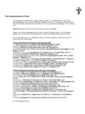
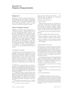
7 Flat Channel A MoCA channel with power magnitude variation of less than dB and group-delay variation of less than 2 ns across any MoCA channel with no added noise, interference, or multipath. Copyright 2015 MoCA Alliance Page 5 of 34 Physical Network Model Typical in-home coaxial networks are configured as a branching tree topology. The point of connection to the first splitter is called the Root Node. The MoCA nodes inside the home communicate with each other by having their signals traverse across one or more splitters. The signal path transmission between two MoCA nodes is the superposition of several individual paths. Each individual signal path may have a different magnitude and delay resulting in an aggregate signal path with frequency nulls, large attenuation, and significant delay spread.
8 The MoCA Network will operate under these channel conditions. Figure 1-1: A Typical In-home MoCA Network Set Top or TV N:1 Splitter Set Top or TV Root Node N:1 Splitter MoCA Node SPLITTER JUMPING IN-HOME 2-WAY COAXIAL PATH N:1 Splitter Cable Modem SPLITTER & WIRING CLOUD SPLITTER & WIRING CLOUD A B < 300 feet from Multi-Tap or ONT to Root Node < 50 feet from ODU to Root Node < 300 feet, < 25 dB root node to node Device MoCA Node MoCA Node MoCA Node SPLITTER JUMPING Multi-Tap/ONT/ODU Copyright 2015 MoCA Alliance Page 6 of 34 2 MoCA Reference Specification MoCA Frequency Plan The following subsections define the bands of operation supported by this Specification . The specified requirements are referenced at the F-connector at the output of any filter required by the Device for proper operation.
9 A minimum network isolation of 9 dB (5 dB minimum splitter isolation + 4 dB minimum cable loss, representing a worst case condition) is assumed between the F-connector of MoCA Device and any other Device on the network. MoCA Extended Band D Frequency Plan This section specifies the frequency plan for MoCA single and bonded-pair channels operation in extended band D (ExD). The extended band D is defined between 1125 MHz and 1675 MHz (550 MHz wide), and extends the high frequency of the existing MoCA 1 band D by 150 MHz. Primary Channels (100 MHz BW) in extended band D are centered on a 25 MHz grid. Bonded-pair channels (225 MHz BW) have a fixed 25 MHz gap between them and tune together as a block where both the Primary Channel and Secondary Channels are centered on the 25 MHz grid.
10 The MoCA frequency plan defines, within the new extended band D, two sub-bands for independent network operation. These sub-bands comprise the D-low and D-high, as follows: Sub-band D-Low (DL): 1125 to 1225 MHz edge to edge (100 MHz wide) Sub-band D-High (DH): 1350 to 1675 MHz edge to edge (325 MHz wide) Guard-band between sub-bands: 1225 to 1350 MHz (125 MHz wide) Figure 2-1 illustrates the MoCA frequency plan in extended band D when a single network is configured in the band. Figure 2-2 illustrates the MoCA frequency plan in extended band D in order to support two MoCA Networks in the band. Table 2-1 specifies the allowed center frequencies of the Primary Channel, Secondary Channel, and Beacon Channel, in the extended band D as well as the center frequencies which apply to sub-bands D-Low and D-High.