Transcription of Complementary N- and P-Channel 60 V (D-S) MOSFET
1 vishay SiliconixSi1029 XDocument Number: 71435S10-2432-Rev. C, N- and P-Channel 60 V (D-S) MOSFETFEATURES Halogen-free According to IEC 61249-2-21 Definition TrenchFET Power MOSFETs Very Small Footprint High-Side Switching Low On-Resistance: N-Channel, P-Channel , 4 Low Threshold: 2 V (typ.) Fast Switching Speed: 15 ns (typ.) Gate-Source ESD Protected: 2000 V Compliant to RoHS Directive 2002/95/ECBENEFITS Ease in Driving Switches Low Offset (Error) Voltage Low-Voltage Operation High-Speed Circuits APPLICATIONS Replace Digital Transistor, Level-Shifter Battery Operated Systems Power Supply Converter Circuits PRODUCT SUMMARY VDS (V)RDS(on) ( )ID (mA)N-Channel 60 at VGS = 10 V 5003 at VGS = V 200P-Channel - 60 4 at VGS = - 10 V - 5008 at VGS = - V - 25 Notes.
2 A. Surface mounted on FR4 board. b. Pulse width limited by maximum junction temperature. Marking Code: HTo p View31D2G2S15246D1S2G1SC-89 Ordering Information: Si1029X-T1-GE3 (Lead (Pb)-free and Halogen-free)ABSOLUTE MAXIMUM RATINGS (TA = 25 C, unless otherwise noted)Parameter Symbol N-Channel P-Channel Unit 5 sSteady State 5 sSteady State Drain-Source Voltage VDS60- 60 VGate-Source Voltage VGS 20 Continuous Drain Current (TJ = 150 C)
3 ATA = 25 CID320305- 200- 190mATA = 85 C230220- 145- 135 Pulsed Drain Currentb IDM650- 650 Continuous Source Current (Diode Conduction)aIS450380- 450- 380 Maximum Power Dissipationa TA = 25 CPD280250280250mWTA = 85 C145130145130 Operating Junction and Storage Temperature Range TJ, Tstg- 55 to 150 CGate-Source ESD Rating (HBM, Method 3015) ESD2000V Number: 71435S10-2432-Rev. C, 25-Oct-10 vishay SiliconixSi1029 XNotes:a. Pulse test; pulse width 300 s, duty cycle 2 %.b. Guaranteed by design, not subject to production testing.
4 C. Switching time is essentially independent of operating beyond those listed under Absolute Maximum Ratings may cause permanent damage to the device. These are stress ratings only, and functional operationof the device at these or any other conditions beyond those indicated in the operational sections of the specifications is not implied. Exposure to absolute maximumrating conditions for extended periods may affect device (TJ = 25 C, unless otherwise noted)Parameter Symbol Test Conditions StaticDrain-Source Breakdown VoltageVDSVGS = 0 V, ID = 10 A N-Ch60 VVGS = 0 V, ID = - 10 A P-Ch- 60 Gate Threshold VoltageVGS(th)
5 VDS = VGS, ID = 250 A N-Ch1 = VGS, ID = - 250 A P-Ch- 1- LeakageIGSSVDS = 0 V, VGS = 5 V N-Ch 50 nAP-Ch 100 VDS = 0 V, VGS = 10 V N-Ch 150 P-Ch 200 Zero Gate Voltage Drain CurrentIDSSVDS = 50 V, VGS = 0 V N-Ch 10 VDS = - 50 V, VGS = 0 V P-Ch - 25 VDS = 50 V, VGS = 0 V, TJ = 85 C N-Ch 100 VDS = - 50 V, VGS = 0 V, TJ = 85 C P-Ch - 250On-State Drain CurrentaID(on) VDS = 10 V, VGS = V N-Ch500 mAVDS = - 10 V, VGS = - V P-Ch- 50 VDS = V, VGS = - V N-Ch800 VDS = - 10 V, VGS = - 10 V P-Ch- 600 Drain-Source On-State ResistanceaRDS(on)
6 VGS = V, ID = 200 mA N-Ch 3 VGS = - V, ID = - 25 mA P-Ch 8 VGS = 10 V, ID = 500 mA N-Ch = - 10 V, ID = - 500 mA P-Ch 4 VGS = 10 V, ID = 500 mA, TJ = 125 CN-Ch = - 10 V, ID = - 500 mA, TJ = 125 C P-Ch 6 Forward Transconductanceagfs VDS = 10 V, ID = 200 mA N-Ch 200 msVDS = - 10 V, ID = - 100 mA P-Ch 100 Diode Forward VoltageaVSDIS = 200 mA, VGS = 0 V N-Ch VIS = - 200 mA, VGS = 0 V P-Ch - Gate ChargeQg N-ChannelVDS = 10 V, VGS = V, ID = 250 mAP-ChannelVDS = - 30 V, VGS = - 15 V, ID = - 500 mAN-Ch 750 pCP-Ch 1700 Gate-Source ChargeQgs N-Ch 75 P-Ch 260 Gate-Drain ChargeQgd N-Ch 225 P-Ch 460 Input CapacitanceCiss N-ChannelVDS = 25 V, VGS = 0 V, f = 1 MHzP-ChannelVDS = - 25 V, VGS = 0 V.
7 F = 1 MHzN-Ch 30 pFP-Ch 23 Output CapacitanceCoss N-Ch 6 P-Ch 10 Reverse Transfer CapacitanceCrss N-Ch 3 P-Ch 5 Tu r n - O n T i m ectON N-ChannelVDD = 30 V, RL = 150 ID 200 mA, VGEN = 10 V, Rg = 10 N-Ch 15 nsP-Ch 20 Turn-Off TimectOFFP-ChannelVDD = - 25 V, RL = 150 ID - 165 mA, VGEN = - 10 V, Rg = 10 N-Ch 20 P-Ch 35 Document Number: 71435S10-2432-Rev.
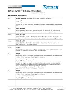
8 C, SiliconixSi1029XN-CHANNEL TYPICAL characteristics (TA = 25 C, unless otherwise noted)Output CharacteristicsOn-Resistance vs. Drain CurrentGate Drain-to-Source Voltage (V)- Drain Current (A)IDVGS = 10 V thru 7 V3 V5 V4 V6 Drain Current (mA)VGS = VVGS = 10 V- On-Resistance (RDS(on)) = 10 VID = 250 mA-Gate-to-Source Voltage (V)Qg- Total Gate Charge (nC)VGST ransfer CharacteristicsCapacitanceOn-Resistance vs. Junction Temperature030060090012000123456 VGS- Gate-to-Source Voltage (V)- Drain Current (mA)IDTJ = - 55 C125 C25 C010203040500510152025 VDS- Drain-to-Source Voltage (V)C-Capacitance (pF)CrssCossCissVGS= 0 Vf = 1 50- 250255075100125150TJ-Junction Temperature ( C)VGS = 10 V at 500 mAVGS = Vat 200 mA(Normalized)- On-Resistance RDS(on) Number: 71435S10-2432-Rev.
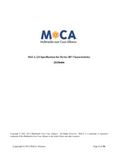
9 C, 25-Oct-10 vishay SiliconixSi1029XN-CHANNEL TYPICAL characteristics (TA = 25 C, unless otherwise noted)Source-Drain Diode Forward = 25 CTJ = 125 CVSD-Source-to-Drain Voltage (V)-Source Current (A)IS10TJ = - 55 CVGS = 0 VOn-Resistance vs. Gate-to-Source Voltage0123450246810 VGS- Gate-to-Source Voltage (V)ID = 500 mAID = 200 mA- On-Resistance (RDS(on))Threshold Voltage Variance Over TemperatureVariance (V)VGS(th) 50- 250255075100125150ID = 250 A TJ-Junction Temperature ( C)Document Number: 71435S10-2432-Rev.
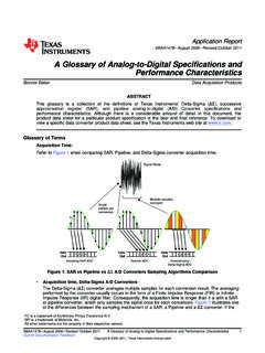
10 C, SiliconixSi1029XP-CHANNEL TYPICAL characteristics (TA = 25 C, unless otherwise noted)Output CharacteristicsOn-Resistance vs. Drain CurrentGate Drain-to-Source Voltage (V)- Drain Current (A)IDVGS = 10 V5 V4 V6 V7 V8 V04812162002004006008001000I - Drain Current (mA)VGS = VVGS = 10 V- On-Resistance (RDS(on))VGS = 5 = 500 mA-Gate-to-Source Voltage (V)Qg- Total Gate Charge (nC)VGSVDS = 30 VVDS = 48 VTransfer CharacteristicsCapacitanceOn-Resistance vs. Junction Temperature030060090012000246810 VGS- Gate-to-Source Voltage (V)- Drain Current (mA)IDTJ = - 55 C125 C25 C08162432400510152025 VDS- Drain-to-Source Voltage (V)C-Capacitance (pF)CrssCossCissVGS= 0 50- 250255075100125150TJ-Junction Temperature ( C)VGS = 10 V at 500 mAVGS = V at 25 mA(Normalized)- On-Resistance RDS(on) Number: 71435S10-2432-Rev.