Transcription of MODEL 2900 Downflow - FleckValves
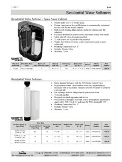
1 IMPORTANT: Fill in pertinent information on page 2 for future 2900 DownflowService ManualMODEL 2900 Job Specification SheetPrinted in JOB NO. _____ MODEL NO. _____ WATER TEST _____ CAPACITY PER UNIT_____MAX. _____PER REGENERATION MINERAL TANK SIZE _____ BRINE TANK SIZE & SALT SETTING PER REGENERATION:_____Page 2 2900 CONTROL VALVE SPECIFICATIONS1) Type of Timer (see pages 18-21)A) 7 day or 12 dayB) * 1,250 to 21,250 gallon meter or* 6,250 to 106,250 gallon meter* Other_____ C) Meter Wiring Package1) System #4 - 1 tank; 1 meter; immediate or delayed regeneration2) System #5 - 2 tanks; 2 meters; interlock3) System #6 - 2 tanks; 1 meter; series regeneration4) System #7 - 2 tanks; 1 meter; alternator2) Timer Program Settings (see pages 18 and 19)A) Backwash _____ ) Brine & Slow Rinse _____ ) Rapid Rinse _____ ) Brine Tank Refill _____ ) Drain Line Flow Controllergpm4) Brine Line Flow Controller -_____5) Injector Size # _____6) A) Hard Water By-PassB) No Hard Water By-PassPrinted in 3 MODEL 2900 General Commercial Pre-Installation Check ListWATER PRESSURE: A minimum of 25 pounds of water pressure is required for regeneration valve to FACILITIES: A continuous 110 volt, 60 Hertz current supply is required.
2 Make certain the current supplyis always hot and cannot be turned off with another PLUMBING: Condition of existing plumbing should be free from lime and iron buildup. Piping that is built upheavily with lime and/or iron should be replaced. If piping is clogged with iron, a separate iron filter unit should beinstalled ahead of the water OF SOFTENER AND DRAIN: The softener should be located close to a VALVES: Always provide for the installation of a by-pass : Water pressure is not to exceed 120 , water temperature is not to exceed 100 F, and the unit cannot besubjected to freezing Instructions1. Place the softener tank where you want to install the unit making sure the unit is level and on a firm base.(Maximum 4 feet apart for twin units.)2. All plumbing should be done in accordance with local plumbing codes.
3 The pipe size for the drain line should be thesame size as the drain line flow control female connection. Water meters are to be installed on soft water units with (1) one meter shall be installed on common soft water outlet of Solder joints near the drain must be done prior to connecting the Drain Line Flow Control fitting. Leave at least 6 between the DLFC and solder joints when soldering when the pipes are connected on the DLFC. Failure to do thiscould cause interior damage to the Teflon tape is the only sealant to be used on the drain fitting. The drain from twin units may be run through acommon Make sure that the floor is clean beneath the salt storage tank and that it is Place approximately 1 of water above the grid plate (if used) in your salt tank. Salt may be placed in the unit at On units with a by-pass, place in by-pass position.
4 Turn on the main water supply. Open a cold soft water tapnearby and let run a few minutes or until the system is free from foreign material (usually solder) that may haveresulted from the Place the by-pass in service Manually index the softener control into service position and let water flow into the mineral tank. When water flowstops, open a cold water tap nearby and let run until air pressure is Electrical: All electrical connections must be connected according to codes. Use electrical conduit if meter systems and Twin meter system wiring diagrams are on pages Plug into power supply. Printed in 4 MODEL 2900 Hard water enters unit at valve inlet and flows down thru the mineral in the mineral water enters center tube thru the bottom distributor then flows up thru thecenter tube around the piston and out the side outlet of the valve.
5 Hard water enters unit at valve inlet flows thru service adapterfor by pass, and up thru coupling to regenerating valve inlet Itthen flows thru the regenerating valve piston down the centertube thru the bottom distributor and up thru the mineral around the piston and out the drain line. If optional no hard waterby pass piston is used water flow to outlet is prevented by anextended section of the service piston which closes the outletport from by pass water until the end of rapid rinse. Hard water enters unit at valve inlet flows up into injectorhousing and down thru nozzle and orifice to draw brine fromthe brine tank brine flows down thru mineral and enters thecenter tube thru bottom distributor flows up thru center tube around the piston and out thru the drain line. 13 SERVICE POSITIONBACKWASH POSITIONBRINE POSITION2 BRINE VALVEFLOW CONTROLINLETOUTLETBRINETANKRESINTANKINLE TDRAINOPTION:NO HARD WATER BY PASSBRINE VALVEFLOWCONTROLDRAININLETOUTLETINLETBRI NETANKRESINTANKBRINE VALVEFLOW CONTROLINLETOUTLETBRINETANKDRAININLETRES INTANKP rinted in 5 MODEL 290046 SLOW RINSE POSITIONBRINE TANK FILL5 RAPID RINSEHard water enters unit at valve inlet flows up into injector housing and down thru nozzle and orifice around the piston down thru mineral enters center tube thru bottom distributor flows upthru center tube around piston and out thru the drain water flows thru the regenerating valve directly downthru the mineral into the bottom distributor and up thru thecenter tube around the piston and out the drain line.
6 Hard water flows thru the service valve and down thru themineral. Conditioned water enters the bottom distributor flowsup the center tube around the piston to the outlet Hard waterflows to the regenerating valve thru the injector housing andbrine valve to fill the brine VALVEFLOW CONTROLDRAINOUTLETINLETBRINETANKINLETRES INTANKBRINE VALVEFLOW CONTROLINLETOUTLETDRAININLETBRINETANKRES INTANKBRINE VALVEFLOW CONTROLINLETOUTLETBRINETANKRESINTANKDRAI NINLETP rinted in 6 MODEL 2900 Control Drive Assembly(See opposite page for parts list)12345678910111215161718192021222324 25262728293334353633 Printed in 7 MODEL 2900 Control Drive AssemblyParts ListItem .. 1 .. 40264 .. Back Plate w/ Thumb Screws2.. 1 .. 15226-6.. Terminal Block3.. 2 .. 15250 .. Label - Terminal Block4.. 2 .. 13296 .. Screws - Terminal Block - #6-20 x 1/2 5.
7 1 .. 13547-01.. Strain Relief6.. 1 .. 40084-12.. Power Cord, 120V., 12 Ft. 7.. 1 .. 11667 .. Wire Harness8.. 1 .. Timer Assembly-Specify 3000, 3200, or 3210 Series9.. 2 .. 14923 .. Micro Switch Screw - #4-40 x 1 10 .. 1 .. 10774 .. Motor Bracket11 .. 1 .. 10769 .. Motor 120V., .. 1 .. 19291-020.. Designer Cover, 1 Piece15 .. 5 .. 10872 .. Motor Mount Screw - #8-32 x 5/16 16 .. 3 .. 10218 .. Micro Switch17 .. 3 .. 10302 .. Insulator18 .. 1 .. 10909 .. Connecting Rod Clip19 .. 2 .. 10250 .. Retaining Ring20 .. 1 .. 10621 .. Connecting Rod 21 .. 2 .. 10231 .. Drive Mount Screw22 .. 1 .. 60160-10.. Drive Cam - Separate Time Fill23 .. 2 .. 10338 .. Drive Roll Pin24 .. 1 .. 13366 .. Drive Bearing25 .. 2 .. 11805 .. Micro Switch Screw26 .. 1 .. 12777 .. Brine Valve Cam27 .. 1 .. 11826.
8 Motor Bracket - Brine Side28 .. 1 .. 14822 .. Motor Lead Wires - Pigtail29 .. 1 .. 15216 .. Meter Cable33 .. 1 .. 15879 .. Cable Guide, Assembly34 .. 1 .. 17421 .. Plug, Heyco35 .. 2 .. 13741 .. Plug, Heyco36 .. 1 .. 14924 .. Strain Relief, Harness37 .. 2 .. 10300 .. Screw, Timer Mounting - Not ShownPrinted in 8 MODEL 2900 Service Assemblies(See opposite page for parts list)Printed in 9 MODEL 2900 Service AssembliesParts ListItem .. 1 .. 18697-01.. Back Plate1 .. 18697-13.. Back Plate (19 pin connector)1 .. 18697-14.. Back Plate (9 pin connector)2.. 1 .. 18748 .. Plug, .750 Hole3.. 1 .. 18720 .. Pipe Plug, 1/2-14 NPT4.. 3 .. 18747 .. Plug, .190 Hole5.. 1 .. 17967 .. Fitting, Liquid Tight6.. 1 .. 17845-02.. Pin, Hinge7.. 5 .. 10300 .. Screw8.. 1 .. 18750 .. Bracket, Terminal9.
9 1 .. 15226-X.. Terminal Strip (X denote number of terminals)10 .. 2 .. 10299 .. Screw, Terminal Strip11 .. 2 .. 15250 .. Label, Terminal Strip12 .. 2 .. 12732 .. Nut, Terminal Strip13 .. 1 .. 17831-01.. Holder, Battery, 9V14 .. 1 .. 18716-01.. Seal, Cover15 .. 4 .. 19203 .. Screw, Window16 .. 1 .. 18745 .. Window17 .. 1 .. 18615-02.. Seal, Window18 .. 1 .. 18670-02.. Cover, Hinged, Black1 .. 18670-07.. Cover, Hinged, Blue19 .. 1 .. 18744 .. Screw, Cover20 .. 5 .. 10872 .. Screw, Motor21 .. 1 .. 60150-10.. Cam, Drive STF22 .. 1 .. 10909 .. Pin, Cam23 .. 2 .. 14923 .. Screw, Switch24 .. 4 .. 10302 .. Insulator253 .. 10218 .. Micro Switch26 .. 2 .. 10231 .. Screw, Motor Bracket27 .. 1 .. 10774 .. Bracket, Motor28 .. 1 .. 10769 .. Motor, 110V 60 Hz1 .. 12292 .. Motor, 230V 50/60 Hz1.
10 13383 .. Motor, 24V 50 Hz1 .. 15073 .. Motor, 24V 60 Hz29 .. 1 .. 11826 .. Bracket, Motor30 .. 1 .. 12777 .. Cam, Brine Valve31 .. 2 .. 10338 .. Pin, Roll32 .. 2 .. 11805 .. Screw, Switch33 .. 1 .. 11667 .. Wire Harness, Drive Motor (Systems 4, 5 & 6)34 .. 1 .. 14822 .. Wire Harness, Upper Drive (Systems 4, 5 & 6)35 .. 1 .. 15926 .. Wire Harness, Lower Drive (System 4)36 .. 1 .. 14827 .. Wire Harness, Lower Drive (Systems 5 & 6)37 .. 1 .. 16564 .. Wire Harness, Upper Drive (System 7)38 .. 1 .. 15938 .. Wire Harness, Lower, Lead Valve (System 7)39 .. 1 .. 15936 .. Wire Harness, Lower, Lag Valve (System 7)40 .. 1 .. 19009 .. Cable, Interlock, 9 Pin Connector (Systems 5, 6, 7)41 .. 1 .. 19010 .. Receptacle, Interlock, 9 Pin Connector(Systems 5, 6 & 7)Printed in 10 MODEL 2900 Adapter Control Drive(See opposite page for parts list)123456789101112131415161718 Printed in 11 MODEL 2900 Adapter Control DriveParts ListItem.