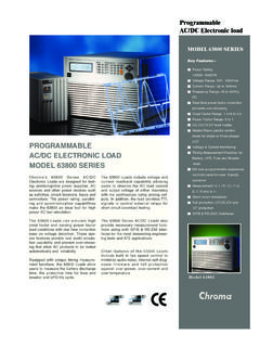
Transcription of MODEL 63800 SERIES - Chroma Systems Solutions, Inc.
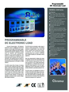
1 All specifications are subject to change without notice. Please visit our website for the most up to date electronic loadChroma's 63800 SERIES AC& dc electronic Loads are designed for testing Uninterruptible Power Supplies(UPS), Off-Grid Inverters, AC sources and other power devices such as switches, circuit breakers, fuses and Chroma 63800 Loads can simulate load conditions under high crest factor and varying power factors with real time compensation even when the voltage waveform is distorted. This special feature provides real world simulation capability and prevents over-stressing thereby gives reliable and unbiased test 63800 's state of the art design uses DSP technology to simulate non-linear rectified loads with its unique RLC operation mode.
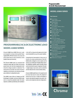
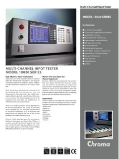
2 This mode improves stability by detecting the impedance of the UUT and dynamically adjusting the load 's control bandwidth to ensure the system's measurements allow users to monitor the output performance of the UUT. Additionally, voltage & current signals can be routed to an oscilloscope through analog outputs. The GPIB/RS232 interface options provide remote control & monitor for system integration. The built-in digital outputs may also be used to control the external relays for short circuit (crowbar) 's 63800 Loads feature in fan speed control to ensure low acoustic noise. The diagnosis/protection functions include self-diagnosis routines and protection against over-power, over-current, over-temperature and over-voltage Features : programmable AC& dc electronic LOADMODEL 63800 SERIESMODEL 63800 SERIES Power Rating : 1800W, 3600W, 4500W Voltage Range : 50V ~ 350 Vrms Current Range : Up to 18 Arms, 36 Arms, 45 Arms Peak Current : Up to 54A, 108A, 135A Parallel / 3-Phase Function Frequency Range : 45 ~ 440Hz, DC Crest Factor Range : ~ Power Factor Range : 0 ~ 1 lead or lag (Rectified mode) CC, CR, CV, CP for DC Loading Constant & Rectified load Modes for AC Loading Analog Voltage & Current Monitor Timing Measurement for Battery, UPS, Fuse and Breaker tests Measurement : V, I, PF, CF, P, Q, S, F, R, Ip+/- and THDv Short circuit simulation Full Protection.
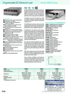
3 OP, OC, OT protection and OV alarm GPIB & RS-232 interfacesRS-232 GPIBC omplete AC & DC load SimulationsChroma's 63800 AC/ dc electronic load is designed for both AC & DC load Simulations. Illustrated below are the various load modes which are available:AC load SimulationAC load SimulationDC load SimulationConstant load ModesCC ModeCR ModeCP ModeRectified load ModesCR ModeCV ModeCP ModeCC ModeRectified ModeRLC ModeCP ModeInrush ModeConstant load ModesThe Constant load Modes allow users to set the following operating modes : CC, CR and CP mode. The CC & CP modes in this category allow users to program PF or CF, or both. For CR mode the PF is always set to both the PF & CF of the loading current are programmed, the 63800 load controls power factor from 1 to 0 by shifting the current (with CF defined) relative to the input voltage to get the desired displacement power factor.
4 The power factor range is limited based on the crest factor programmed. If the programmed PF is positive then the current will lead the voltage waveform and when PF is set negative, the current will lag the voltage waveform. (See below)The MODEL 63800 AC/ dc electronic load provides two unique operating modes for AC load simulation; (1) Constant load Modes and (2) Rectified AC load Modes. Each are described seen in Figure 1, for a crest factor of , the programmed power factor can only be 1 if the input voltage is a sine-wave. However, for a CF of , the acceptable PF ranges from to ; for CF = 3, the PF can then be set from to , etc. So, higher crest factors enable a wider range of power 1: Crest Factor vs. Power Factor control RangeCFI = I peak / I rmsPF = True power / Apparent powerPFCFIM odel 63800 Rectified AC load ModesThe 63800 AC/ dc electronic load provides unique capability to simulate non-linear rectified loads for a wide range of testing applications.
5 There are three load modes available for rectified load simulations : RLC, CP and Inrush 3: Actual RLC CircuitFigure 4: Simulated RLC ModeFigure 5: CC ModeFigure 6: Inrush Current ModeDC load SimulationChroma's 63800 DC load simulation includes four load modes : constant current, constant resistance, constant voltage and constant power as depicted current Constant resistance Constant voltage Constant powerCC, CR, CP mode can be used for regulated voltage power supply testing. For battery charger, CV mode may help to check its current special DC Rectified mode is included to simulate the loading behavior of distributed inverters. Many inverter designs, although its input is DC, show an input current and will show rectified pattern.
6 This unique load mode makes the Chroma 63800 load ideal for Fuel Cell, PV module/array and Battery 2 : Typical Rectified CircuitVIVIVIVIF igure 2 shows the typical MODEL of a rectifier input. Under RLC mode, users can set the RLC values to 100% and simulate the behavior of the actual UUT. Figure 3 & 4 compares the voltage and loading waveforms between the actual RLC built circuit and the simulated rectified circuit using Chroma 's RLC load mode. The waveform of the 63800 in RLC mode looks almost identical to the waveform of the actual hardware circuit. The waveform obtained under CC mode with the same loading crest factor shown in Figure 5 is considerably different than the waveform of actual hardware addition, traditional AC loads can only use CR mode to test discontinuous square or quasi-square wave UUTs because CC and CP are all active loadings, which require a defined frequency.
7 It's very difficult to detect the frequency of a discontinuous square or quasi-square wave. The RLC mode of the 63800 load is actually simulating passive loading and it doesn't require a defined frequency, therefore it allows the user to simulate loading in modes other than just CR. Using a discrete RLC network may solve the problem; however, the component weight, size and limited RLC values make it inconvenient for testing. In contrast, Chroma 's 63800 RLC mode is much more flexible and provides a complete host of production line testing, most users may not know the required RLC values but do know the UUTs power rating and PF values. In this case, the CP mode is ideal for test engineers. Under CP mode, the 63800 built-in algorithm will find the best way to get the RLC values automatically according to the power rating and PF value set by the user.
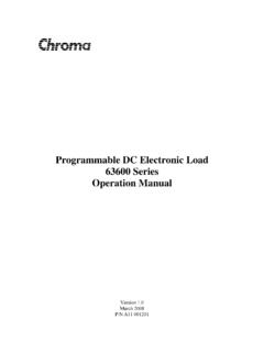
8 To avoid overstressing the UUT, both RLC and CP modes will gradually increase the load current up to the programmed loading current shown in Figure 4, simulating actual RLC circuit loading as shown in Figure 3. This will alleviate the sudden voltage drop from the constant current loading mode as shown in Figure inrush current simulation, the 63800 provides an Inrush Current mode that allows the user to set different inrush current amplitude and voltage phase angle where the inrush current R O G R A M M A B L E A C & D C E L E C T R O N I C L O A DFigure 8: Fixed BandwidthFigure 9: With ABAC omprehensive MeasurementsFigure 7:Transfer time for Off-Line UPSA utomatic Bandwidth Adjustment (ABA)The examples on the right compare voltage and current waveforms using a traditional fixed bandwidth (@15kHz) load and the Chroma 63800 load for UPS load simulation.
9 A significant difference can be observed with and without the the UUT, such as one shown in Figure 8, has a higher output impedance, the current waveform will not be stable without ABA. In most cases, the loading current will be oscillating and spoil the using active load mode (CC, CP), traditional AC loads operate under fixed bandwidth. When the load is working at low control bandwidth it will limit the load from simulating high crest factor loading. Conversely, increased control bandwidth will influence the control loop stability especially when the UUT output impedance is high. To resolve this problem of traditional AC loads, the Chroma 63800 AC/DC load dynamically adjusts the operating bandwidth by detecting the impedance* of the UUTs to alleviating the risk of system 1: A test current will be programmed prior the actual loading defined by user for impedance / 3-Phase ControlThe 63800 SERIES provides parallel and 3-phase functions for high power and three phase applications.
10 All the models within the 63800 SERIES can be used together for both parallel and 3-phase functions as well as paralleled AC load units in a 3-phase configuration, providing excellent flexibility and cost savings for the 63800 SERIES AC load . Parallel and 3-phase controls are made easy by linking the AC load units together and control of all AC load units is performed through the Master Unit. Connections of parallel and 3-phase functions are shown in Figures 10, 11 and 10: Parallel connectionFigure 11: Parallel/3-Phase Y connectionFigure 12: Parallel/3-Phase Delta connectionChroma's 63800 SERIES AC/ dc electronic Loads include built-in 16-bits precision measurement circuits to measure the steady-state and transient responses for true RMS voltage, true RMS current, true power(P), apparent power(S), reactive power(Q), crest factor, power factor, THDv and peak repetitive additional to these discrete measurements, two analog outputs, one for voltage and one for current, are provided as a convenient means of monitoring these signals via an external MeasurementTiming parameters are critical to many products such as UPS's Breakers and Fuses.