Transcription of Programmable DC Electronic Load - Farnell element14
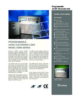
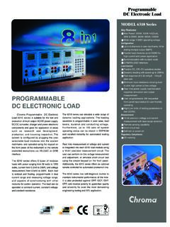
1 Programmable DC Electronic Load8600 SeriesData data subject to change B&K Precision Corp. 2015 The 8600 Series Programmable DC electronicloads provide the performance of modular systemDC Electronic loads in a compact benchtop formfactor. With fast transient operation speeds andhigh 16-bit measurement resolution, these standalone DC loads can be used for testing andevaluating a variety of DC sources such as DCpower supplies, DC-DC converters, batteries,battery chargers, and photovoltaic DC loads can operate in constant current(CC), constant voltage (CV), constant resistance(CR), or constant power (CW) mode and be configured to provide a dynamically changingload to the DC source with fast load switchingtimes. Versatile internal, external, and remotetriggering options allow the dynamic load behavior to be synchronized with other productivity by saving your test parameters into any one of the 100 memoryFeatures Voltage range up to 500 V Current range up to 60 A CC/CV/CR/CW operating modes 16-bit voltage and current measurement system providing 1 mV / mA resolution Transient mode up to 25 kHz in CC mode List mode function Store and recall up to 100 setups Adjustable slew rate in CC mode Flexible triggering options via front panel, external input, timer, or bus Built-in battery test function with voltage level, capacity level, and timer stop conditions Test modes to validate the OCP/OPP protection functions of a power supply CR-LED mode to simulate the loading behavior of typical LEDs Remote sense Analog current control and monitoring Thermostatically controlled fan Standard USB (USBTMC-compliant)
2 , RS232, and GPIB interfaces supporting SCPI commands for remote control OVP/OCP/OPP/OTP including local and remote reverse voltage (LRV/RRV) protection Compact 19 half-rack form factor allows forside-by-side rack mounting of two unitsModel860086018602 Power150 W250 W200 WOperating Voltage0 120 V0 120 V0 500 VRated Current0 30 A0 60 A0 15 Aareas for quick system recall. All load parameterssuch as voltage, current, slew rate, and widthcan be set via the front panel or programmedremotely. The 8600 Series provides standardUSB (USBTMC-compliant), GPIB, or RS-232serial interfaces for remote communication. To ensure the reliability of your testing, the 8600 Series provides a power-on system self-test andnumerous protection features: overtemperature(OTP), overvoltage (OVP), overcurrent (OCP),overpower (OPP), and local/remote reverse voltage (LRV/RRV) ApplicationsThe 8600 Series provides a built-in battery testmode to measure the ampere-hour (Ah)
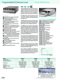
3 Characteristic of a battery and a unique CR-LEDmode to simulate the loading behavior of a typical DC Electronic Load8600 Series2 Bright dual-line displayThe 8600 Series display shows both measured inputvalues and set parameters panelRear panelRotary controlknobCooling fanRS-232interfaceUSBinterfaceGPIB interfaceCurrent monitor BNC outputOutputs a 0-10 V signal that follows0-full range of the input terminal blockExternal trigger, external analog programming,external input On/Off control, voltage fault pin,and remote sense terminalsLine voltage selectorNumeric keypadFunction keysCursor keysLoad input terminalIntuitive user interfaceThe numeric keys and rotary knob provide a convenient interface for setting the operating mode and desired current, voltage, and resistance levels quicklyand precisely. High current test lead accessory model DC Electronic Load8600 Series3 Flexible operation Automatic test modeThe 8600 Series can execute multiple testsequences in automatic test mode.
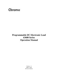
4 Up to 100different sequences can be linked to run steps ofvarious operating modes and loading sequence can also be programmed withupper and lower limit Pass/Fail criteria. Whenapplied in production testing, you can easilyjudge whether the test parameters of yourdevices are within the specification limits andadjust your process according to the modeNot limited to just switching between two levels,list mode lets you generate more complexsequences of input changes with several differentlevels. Up to 7 groups of list files can be savedand executed in CC mode via internal or externaltrigger. Each list can contain up to 84 steps withvarying slew rates and a minimum width time of20 s per modeUse the load s unique CR-LED operating modeto test LED drivers. This function allows users toconfigure the LED s operating resistance and forward voltage to simulate the loading behaviorof typical voltage operationThe 8600 Series can operate at low voltages for applications such as fuel cell and solar cell = Forward voltage of the LEDRd = LED operating resistanceVo = LED operating voltageIo = LED operating VLED I-V CurveVoltage01234586028600860115304560 Typical minimum operating voltage at full scale current:Transient operation enables the load to periodicallyswitch between two load levels (A/B).
5 A powersupply s regulation and transient characteristic canbe evaluated by monitoring the supply s output voltage under varying combinations of load levels,duty cycle, and slew rate. The 8600 Series cansimulate these conditions in CC, CV, CW, and operationA levelTrigger01234 5678 StepstASlew RateB levelAtIVCC 1 A1 s s sCV 3 VIoVd VoRdCW WCR 2 DC Electronic Load8600 Series4 Powerful communication interfacesThe 8600 Series provides standard GPIB, USB,and RS232 interfaces for remote interfaces offer SCPI and USBTMC standard communication protocols to controlyour Electronic load from a software is provided for front panel emulation,generating and executing test sequences, or logging measurement data without the need towrite source code. Additionally, this applicationsoftware integrates with NI Data Dashboard forLabVIEW apps, which allows users to create acustom dashboard on a tablet computer or smartphone to remotely monitor 8600 Series DC loads via this PC software.
6 Remote monitoring on iOS, Android or Windows 8 compatible tablets or smartphones via NI Data Dashboard for LabVIEW apps Log voltage, current, and power values with timestamp Run transient operation and list mode programs remotely Create an unlimited number of external list files to be executed from PC memoryApplication softwareIn addition to front panel and remote interfacecontrol, current values can also be programmedwith an analog control signal. The electronicloads can be externally controlled from zero tofull scale with a 0-10 V input signal. A BNC output is available on the rear for monitoring the current with a 0-10 V output analog programming andmonitoring interfaceControl the input turn on state for the DC Electronic load by configuring the Von latch function. This can be used to start and stop discharging of a battery or other power source at a specified voltage (Von) latch operationBattery test functionThe built-in battery test function uses CC modeto calculate the battery capacity using a fixedcurrent load discharge.
7 Users can specify cut-offvoltage level, capacity level, and time stop slew rateIn CC mode, users can control the rate or slopeof the change in current in a transient responsetest. Set the slew rate to as slow as A/msor as fast as A/ s depending on the modeland selected current SinkCurrenttASlew RateRise RateA/ sRemote control and programmingTypical battery discharge 8600 Series can measure the rise or fall time from a specified start and stop voltage level ofthe measured input without the need for an oscilloscope. This function can also be used as aninternal timer to count how long the input has been rise and fall time measurementOscilloscope display8600 Series DC Electronic Load8600 Series5 SpecificationsModel860086018602 Input ratingsInput voltage0 120 V0 120 V0 500 VInput currentLow0 3 A0 6 A0 3 AHigh0 30 A0 60 A0 15 AInput power150 W250 W200 WMinimumoperating V at 3 V at 6 A1 V at 3 V at 30 V at 60 V at 15 ACV modeRangeLow0 18 V0 50 VHigh0 120 V0 500 VResolutionLow1 mVHigh10 mVAccuracyLow ( + FS) ( + FS) ( + FS)High ( + FS) ( + FS) ( + FS)CC modeRangeLow0 3 A0 6 A0 3 AHigh0 30 A0 60 A0 15 mAHigh1 mAAccuracyLow ( + FS)High ( + FS)CR 10 10 High10 - k Resolution16 + + SCW modeRange150 W250 W200 WResolution10 + + + FSTransient mode (CC mode)T1 & T2 (1)20 s 3600 s / Resolution.
8 10 sAccuracy5 s + 100 ppmSlew Rate (2) A/ A/ sv012015 Readback voltageRangeLow0 18 V0 18 V0 50 VHigh0 120 V0 120 V0 500 mVHigh1 mVAccuracy ( + FS)Readback currentRangeLow0 3 A0 6 A0 3 AHigh0 30 A0 60 A0 15 mA1 mAAccuracy ( + FS) ( + FS) ( + FS)Readback powerRange150 W250 W200 WResolution10 mWAccuracy (1%+ FS) ( + FS) ( + FS)Protection range (typical)OPP 150 W 250 W 200 WOCPLow A A AHigh 33 A 66 A AOVP 120 V 120 V 500 VOTP185 F (85 C)General (typical)Short circuitCurrent (CC)Low A A AHigh 33/30 A 66/60 A AVoltage (CV)0 VResistance (CR) 35 m 30 m 300 m Input terminal impedance150 k 300 k 1 M AC input110 V/220 V 10%, 50/60 HzOperating temperature32 F to 104 F (0 C to 40 C)Storage temperature14 F to 140 F (-10 C to 60 C)HumidityIndoor use, 95% SafetyEN61010-1:2001, EU Low Voltage Directive 2006/95/ECElectromagnetic compatibilityMeets EMC Directive 2004/108/EC, EN 61000-3-2:2006, EN 61000-3-3:1995+A1:2001+A2:2005EN 61000-4-2/-3/-4/-5/-6/-11, EN 61326-1:2006 Dimensions (W x H x D) x x 14 ( x x mm)Weight11 lbs (5 kg)Three-Year WarrantyStandard accessoriesUser manual, power cord, certificate of calibration & test reportOptional accessoriesModel TLPWR1 high current test leads, IT-E151 rack mount kit(1) Fast pulse trains with large transitions may not be achievable.
9 (2)The slew rate specifications are not warranted, but are descriptions of typical performance. The actualtransition time is defined as the time for the input to change from 10% to 90%, or vice versa, of the programmed current values. In case of very large load changes, from no load to full load , the actualtransition time will be larger than the expected time. The load will automatically adjust the slew rate to fitwithin the range (high or low) that is closest to the programmed value.