Transcription of Modeling,Analysis and Compensation of the Current-Mode ...
1 U-97 APPLICATION NOTEMODELLING, analysis ANDCOMPENSATION OF THECURRENT-MODE CONVERTERA bstractAs Current-Mode conversion increases in popularity, several peculiarities associated with fixed-frequency, peak-currentdetecting schemes have surfaced These include instability above 50% duty cycle, a tendency towards subharmonicoscillation, non-ideal loop response, and an increased sensitivity to noise. This paper will attempt to show that theperformance of any Current-Mode converter can be improved and at the same time all of the above problems reduced oreliminated by adding a fixed amount of slope Compensation to the sensed current INTRODUCTIONThe recent introduction of integrated control circuits designed specificallyfor current mode control has led to a dramatic upswing in theapplication of this technique to new designs. Although the advantages ofcurrent-mode control over conventional voltage-mode control has beenamply demonstrated(l-5), there still exist several drawbacks to a fixedfrequency peak-sensing current mode converter.
2 They are (1) open loopinstability above 50% duty cycle, (2) less than ideal loop responsecaused by peak instead of average inductor current sensing, (3) tendencytowards subharmonic oscillation, and (4) noise sensitivity, particularlywhen inductor ripple current is small. Although the benefits of currentmode control will, in most cases, far out-weight these drawbacks, asimple solution does appear to be available. It has been shown by anumber of authors that adding slope Compensation to the currentwaveform (Figure 1) will stabilize a system above 50% duty cycle. Ifone is to look further, it becomes apparent that this same compensationtechnique can be used to minimize many of the drawbacks stated fact, it will be shown that any practical converter will nearly alwaysperform better with some slope Compensation added to the simplicity of adding slope Compensation - usually a single resistor -adds to its attractiveness.
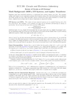
3 However, this introduces a new problem - thatof analyzing and predicting converter performance. Small signal ACmodels for both current and voltage-mode PWM s have beenextensively developed in the literature. However, the slope compensatedor dual control converter possesses properties of both with anequivalent circuit different from yet containing elements of this has been addressed in part by several authors(l,2), therestill exists a need for a simple circuit model that can provide bothqualitative and quantitative results for the power supply 1- A Current-Mode CONTROLLED BUCK REGULATOR WITH SLOPE NOTEU-97 The first objective of this paper is to familiarize the reader with thepeculiarities of a peak-current control converter and at the same timedemonstrate the ability of slope Compensation to reduce or eliminatemany problem areas.
4 This is done in section 2. Second, in section 3, acircuit model for a slope compensated buck converter in continuousconduction will be developed using the state-space averaging techniqueoutlined in (1). This will provide the analytical basis for section 4 wherethe practical implementation of slope Compensation is OPEN LOOP INSTABILITYAn unconditional instability of the inner current loop exists for any fixedfrequency Current-Mode converter operating above 50% duty cycle -regardless of the state of the voltage feedback loop. While sometopologies (most notably two transistor forward converters) cannotoperate above 50% duty cycle, many others would suffer serious inputlimitations if greater duty cycle could not be achieved. By injecting asmall amount of slope Compensation into the inner loop, stability willresult for all values of duty cycle.
5 Following is a brief review of ) DUTY CYCLE < ) DUTY CYCLE > ) DUTY CYCLE > WITH SLOPE COMPENSATIONFIGURE 2- DEMONSTRATION OF OPEN LOOP INSTABILITY IN ACURRENT-MODE 2 depicts the inductor current waveform, IL, of a current-modeconverter being controlled by an error voltage V,. By perturbing thecurrent IL by an amount AI, it may be seen graphically that AI willdecrease with time for D < (Figure 2A), and increase with time forD > (Figure 2B). Mathematically this can be stated asCarrying this a step further, we can introduce a linear ramp of slope -mas shown in Figure 2C. Note that this slope may either be added to thecurrent waveform, or subtracted from the error voltage. This then givesSolving for m at 100% duty cycle givesm > - /zm2(3)Therefore, to guarantee current loop stability, the slope of thecompensation ramp must be greater than one-half of the down slope ofthe current waveform.
6 For the buck regulator of Figure 1, m2 is avoconstant equal to --L Rs, therefore, the amplitude A of the compensatingwaveform should be chosen such thatvoA>TRs L(4)to guarantee stability above 50% duty RINGING INDUCTOR CURRENTL ooking closer at the inductor current waveform reveals two additionalphenomenon related to the previous instability. If we generalize equation2 and plot I, vs nT for all n as in Figure 3, we observe a dampedsinusoidal response at one-half the switching frequency, similar to that ofan RLC circuit. This ring-out is undesirable in that it (a) produces aringing response of the inductor current to line and load transients, and(b) peaks the control loop gain at the switching frequency, producinga marked tendency towards 3- ANALOGY OF THE INDUCTOR CURRENT RESPONSE TOTHAT OF AN RLC has been shown in (1), and is easily verified from equation 2, that bychoosing the slope Compensation m to be equal to -m2 (the down slopeof the inductor current), the best possible transient response is is analogous to critically damping the RLC circuit, allowing thecurrent to correct itself in exactly one cycle.
7 Figure 4 graphicallydemonstrates this point. Note that while this may optimize inductorcurrent ringing, it has little bearing on the transient response of thevoltage control loop 4- FOR THE CASE OF m = - m2, A CURRENT PERTURBATIONWILL DAMP OUT IN EXACTLY ONE SUBHARMONIC OSCILLATIONFor steady state condition we can writeGain peaking by the inner current loop can be one of the mostDml T=(l -D)mzT(8)significant problems associated with Current-Mode controllers. Thispeaking occurs at one-half the switching frequency, and - because ofor-2(9)excess phase shift in the modulator - can cause the voltage feedbackD=r- m2loop to break into oscillation at one-half the switching frequency. ThisBy using (9) to reduce (7), we obtaininstability, sometimes called subharmonic oscillation, is easily detectedas duty cycle asymmetry between consecutive drive pulses in the powerAIL1stage.
8 Figure 5 shows the inductor current of a Current-Mode controllerc\v,=(10)in subharmonic oscillation (dotted waveforms with period 2T).1 -2D(l +rn/m2)Now by recognizing thatis simply a square wave of period 2T, wecan relate the first harmonic amplitude toby the factor 4/n andFIGURE 5- CURRENT WAVE FORM (DOTTED) OF A CURRENT-MODECONVERTER IN SUBHARMONIC determine the bounds of stability, it is first necessary to develop anexpression for the gain of the inner loop at one-half the switchingfrequency. The technique used in (2) will be paralleled for a buckconverter with the addition of terms to include slope LOOP GAIN CALCULATION AT fSReferring to figures 5 and 6, we want to relate the input stimulus, AVe,to an output current,From figure 5, two equations may bewrittenAIL= ADmlT-hDm2T(4)AVc = ADmrT+ADmzT(5)Adding slope Compensation as in figure 6 gives another equationAV, = AVc+2 ADmT(6)Using (5) to eliminate AVc from (6) and solving foryields(7)FIGURE 6- ADDITION OF SLOPE Compensation TO THE CONTROLSIGNAL write the small signal gain at f = /zfs asiL4n-=ve1 -2D(l +m/m2)(11)If we assume a capacitive load of C at the output and an error amplifiergain of A, then finally, the expression for loop gain at f = / fs is4 TALoop gain =l-9 c(12)1 -2D(l +m/m2)
9 USING SLOPE Compensation TO ELIMINATESUBHARMONIC OSCILLATIONFrom equation 12, we can write an expression for maximum erroramplifier gain at f = M fs to guarantee stability asA1 -2D(l +m/mz)max =4T(13)r-6 cThis equation clearly shows that the maximum allowable error amplifiergain, Amax, is a function of both duty cycle and slope Compensation Anormalized plot of Amaxversus duty cycle for several values of slopecompensation is shown in figure 7. Assuming the amplifier gain cannotbe reduced to zero at f = Mfs, then for the case of m = 0 (nocompensation) we see the same instability previously discussed at 50%duty cycle. As the Compensation is increased to m = - /zm2, the pointof instability moves out to a duty cycle of , however in any practicalDUTY CYCLE (D)FIGURE 7-MAXIMUM ERROR AMPLIFIER GAIN AT /2 fs (NORMALIZED) DUTY CYCLE FOR VARYING AMOUNTS OF SLOPECOMPENSATlON.
10 REFER TO EQUATION NOTEU-97system, the finite value of A,,will drive the feedback loop intosubharmonic oscillation well before full duty cycle is reached. If wecontinue to increase m, we reach a point, m = -m2, where themaximum. gain becomes independent of duty cycle. This is the point ofcritical damping as discussed earlier, and increasing m above this valuewill do little to improve stability for a regulator operating over the fullduty cycle PEAK CURRENT SENSING VERSUSAVERAGE CURRENT SENSINGTrue Current-Mode conversion, by definition, should force the averageinductor current to follow an error voltage - in effect replacing theinductor with a current source and reducing the order of the system byone. As shown in Figure 8, however, peak current detecting schemes aregenerally used which allow the average inductor current to vary withduty cycle while producing less than perfect input to output - orfeedforward characteristics.