Transcription of Modular reducing valves HG, KG, JPG-2 and JPG-3
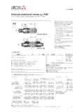
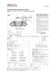
1 Table D140-15/E. Modular reducing valves type HG, KG, JPG-2 and JPG-3 . spool type, ISO 4401 sizes 06, 10, 16 and 25. HG, KG, JPG are pressure reducing valves , spool type , designed to ope- rate in oil hydraulic systems. HG are direct, three way valves ;. KG are double stage , three way valves ;. P1 T1 T1 P1 A JPG are double stage , two way valves . Clockwise rotation increases the pres- sure. HG-031/**/V P T KG-034 Valve size and max flow: HG = size 06 flow up to 50 l/min;. T P. KG = size 10 flow up to 100 l/min;. JPG-2 =size 16 flow up to 250 l/min;. P1 T1 P1 T1. JPG-3 =size 25 flow up to 300 l/min;. Mounting surface: ISO 4401 size 06, 10, 16 and 25. Max pressure: 350 bar for HG. 315 bar for KG and JPG.. Y P T Y P T. JPG-211 JPG-311. 1 MODEL CODE. HG-0 31 / 210 / V ** / *. Seals material, see section : Modular pressure reducing - = NBR. valve, size: PE = FKM. HG-0 = 06 JPG-2 = 16 BT = HNBR. KG-0 = 10 JPG-3 = 25. Series number Options: V = setting adjustment by handwheel instead of a grub screw protected by cap Configuration, see section Only for HG: two way (only for JPG): VF = regulating knob /VS = regulating knob with safety locking 11 = reduced pressure on P port three way (only for HG-0 and KG-0): Pressure range HG KG JPG.
2 31 = reduced pressure on P port 32 = 3 - 32 bar 100 = 20 - 100 bar 100 = 7 - 100 bar 100 = 6 - 100 bar 33 = reduced pressure on A port 50 = 2 - 50 bar 210 = 50 - 210 bar 210 = 8 - 210 bar 210 = 70 - 210 bar 34 = reduced pressure on B port 75 = 10 - 75 bar 2 HYDRAULIC CHARACTERISTICS. Hydraulic configuration HG-031 HG-033 HG-034. JPG-*11. KG-031 KG-033 KG-034. Valve model HG-03*/32 HG-03*/50 HG-03*/75 HG-03*/100 HG-03*/210 KG-03*/100 KG-03*/210 JPG-211/100 JPG-211/210 JPG-311/100 JPG-311/210. Max flow [l/min] 50 100 250 300. Pressure range [bar] 3 32 2 50 10 75 20 100 50 210 7 100 8 210 6 100 70 210 6 100 70 210. Max inlet pressure [bar] 350 315 315 315. Max pressure on port T [bar] 160 160 160 160. D140. 3 MAIN CHARACTERISTICS, SEALS and HYDRAULIC FLUID - for other fluids not included in below table, consult our technical office Assembly position / location Any position Subplate surface finishing Roughness index Ra 0,4 - flatness ratio 0,01/100 (ISO 1101). MTTFd values according to EN ISO 13849 150 years, for further details see technical table P007.
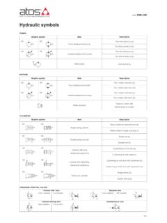
3 Standard execution = -30 C +70 C. Ambient temperature /PE option = -20 C +70 C. /BT option = -40 C +70 C. NBR seals (standard) = -20 C +60 C, with HFC hydraulic fluids = -20 C +50 C. Seals, recommended fluid temperature FKM seals (/PE option)= -20 C +80 C. HNBR seals (/BT option)= -40 C +60 C, with HFC hydraulic fluids = -40 C +50 C. Recommended viscosity 15 100 mm2/s - max allowed range 500 mm2/s Fluid contamination class ISO 4406 class 21/19/16 NAS 1638 class 10, in line filters of 25 mm (b25 >. _ 75 recommended). Hydraulic fluid Suitable seals type Classification Ref. Standard Mineral oils NBR, FKM, HNBR HL, HLP, HLPD, HVLP, HVLPD DIN 51524. Flame resistant without water FKM HFDU, HFDR. ISO 12922. Flame resistant with water NBR, HNBR HFC. 4 DIAGRAMS OF HG-03* based on mineral oil ISO VG 46 at 50 C. 1 = regulated pressure variation versus flow: 1. - between use port and discharge port 3. Regulated pressure [bar]. Differential pressure [bar]. - between inlet port and use port 2 = differential pressure variation versus flow between inlet port and use port 3 = differential pressure variation versus 2.
4 Flow between use port and discharge port [USE T] [IN USE]. Flow [l/min] Flow [l/min]. 5 DIAGRAMS OF KG-03* based on mineral oil ISO VG 46 at 50 C. 1 = regulated pressure variation versus flow: 1. - between use port and discharge port Differential pressure [bar]. Regulated pressure [bar]. - between inlet port and use port 3. 2 = differential pressure variation versus 2. flow between inlet port and use port 3 = differential pressure variation versus flow between use port and discharge port [USE T] [IN USE]. Flow [l/min] Flow [l/min]. 6 DIAGRAMS OF JPG-211 based on mineral oil ISO VG 46 at 50 C. 1 = regulated pressure variation versus flow between inlet port and use port 1 2. 2 = differential pressure variation versus Regulated pressure [bar]. Differential pressure flow between use port and discharge port Flow [l/min] Flow [l/min]. 7 DIAGRAMS OF JPG-311 based on mineral oil ISO VG 46 at 50 C. 1 = regulated pressure variation versus flow between inlet port and use port 1 2. 2 = differential pressure variation versus Regulated pressure [bar].
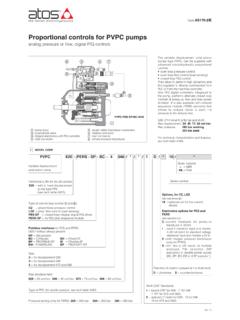
5 Differential pressure flow between use port and discharge port Flow [l/min] Flow [l/min]. 8 INSTALLATION DIMENSIONS OF HG-0 valves [mm]. HG-03*.. A P B. = Pressure gauge port = G 1/4 . Adjustment device for option /V Mass: 2,3 Kg ISO 4401: 2005. Mounting surface: 4401-03-02-0-05. Adjustment device for option /VF and /VS Diameter of ports A, B, P, T: = 7,5 mm Seals: 4 OR 108. View from X. Fastening bolts: n 4 socket head screws M5. The lenght depends on number and type of Modular elements associated. 9 INSTALLATION DIMENSIONS OF KG-0 valves [mm]. KG-03*. CH. 6.. =. =. 50. A P B. =. =. = = = =. 65 70 103 11. = Pressure gauge port = G 1/4 . 184. X. Mass: 3,8 Kg Adjustment device for option /V. ISO 4401: 2005. Mounting surface: 4401-05-04-0-05. Diameter of ports A, B, P, T: = 11,2 mm Seals: 5 OR 2050. View from X. Fastening bolts: n 4 socket head screws M6. The lenght depends on number and type of Modular elements associated. D140. 10 INSTALLATION DIMENSIONS OF JPG-2 valves [mm].
6 JPG-211.. = Pressure gauge port = G 1/4 . Mass: 9 Kg Adjustment device for option /V. ISO 4401: 2005. Mounting surface: 4401-07-07-0-05. Diameter of ports A, B, P, T: = 20 mm Diameter of ports X, Y: 7 mm Seals: 4 OR 130: 2 OR 109. View from X. Fastening bolts: n 4 socket head screws M10 and n 2 M6. The lenght depends on number and type of Modular elements associated. 11 INSTALLATION DIMENSIONS OF JPG-3 valves [mm]. JPG-311.. = Pressure gauge port = G 1/4 Mass: 9 Kg Adjustment device for option /V. ISO 4401: 2005. Mounting surface: 4401-08-08-0-05. Diameter of ports A, B, P, T: = 24 mm Diameter of ports X, Y: 7 mm Seals: 4 OR 130: 2 OR 109. View from X. Fastening bolts: n 6 socket head screws M12. The lenght depends on number and type of Modular elements associated. 02/17.