Transcription of Motor Control Sensor Feedback Circuits
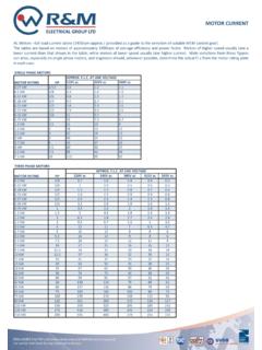
1 2003 Microchip Technology 1 MAN894 INTRODUCTIONS ensors are a critical component in a Motor controlsystem. They are used to sense the current, position,speed and direction of the rotating Motor . Recentadvancements in Sensor technology have improvedthe accuracy and reliability of sensors, while reducingthe cost. Many sensors are now available that integratethe Sensor and signal-conditioning circuitry into a most Motor Control systems, several sensors areused to provide Feedback information on the sensors are used in the Control loop and toimprove the reliability by detecting fault conditions thatmay damage the Motor . As an example, Figure 1 pro-vides a block diagram of a DC Motor Control system toshow the Sensor Feedback provided for a typical list of the sensors that can be used to feedbackinformation to a microcontroller are listed below: Current sensors- Shunt resistor- Current-sensing transformer- Hall effect current Sensor Speed/position sensors- Quadrature encoder- Hall efect tachometer Back EMF/Sensorless Control methodFIGURE 1:Typical DC Motor Block :Jim LepkowskiMicrochip Technology ManagementInputMicrocontrollerDriverMoto rFeedbackTorqueSpeedDirectionCurrentSens orSensors* Speed* Shaft Position* Rotation DirectionPICmicro Motor Control Sensor Feedback CircuitsAN894DS00894A-page 2 2003 Microchip Technology SENSORSThe three most popular current sensors in motorcontrol applications are.
2 Shunt resistors Hall effect sensors Current transformersShunt resistors are popular current sensors becausethey provide an accurate measurement at a low effect current sensors are widely used becausethey provide a non-intrusive measurement and areavailable in a small IC package that combines thesensor and signal-conditioning circuit . Current-sensingtransformers are also a popular Sensor technology,especially in high-current or AC line-monitoringapplications. A summary of the advantages anddisadvantages of each of the current sensors isprovided in Table 2 shows an example of an AC Motor powered bya three-phase inverter bridge circuit . This exampleshows that the composite current of all three InsulatedGate Bipolar Transistor (IGBT) circuit legs can bemeasured with a single shunt resistor, or that thecurrent in each individual leg can be determined withthree shunt resistors.
3 Figure 2 shows a system thatuses shunt resistors. However, Hall effect and current-sensing transformers can also be used to provide thecurrent 1:COMPARISON OF CURRENT SENSING METHODSFIGURE 2:AC Motor Current Sensing MethodShunt ResistorHall EffectCurrent Sensing TransformerAccuracyGoodGoodMediumAccurac y Current-Measuring CapabilityPoorGoodGoodDC Offset ProblemYesNoNoSaturation/Hysteresis ProblemNoYesYesPower ConsumptionHighLowLowIntrusive MeasurementYesNoNoAC/DC MeasurementsBothBothOnly AC ACMotorVDCRSENSEVOUTRSENSE_AVOUT_ARSENSE _BVOUT_BRSENSE_CVOUT_CCurrent Measurement with a Single Shunt ResistorCurrent Measurement with Three Shunt ResistorsIAIBICI = IA+ IB + IC ACMotorVDCIAIBIC 2003 Microchip Technology 3AN894 Shunt ResistorsShunt resistors are a popular current-sensing sensorbecause of their low cost and good accuracy. Thevoltage drop across a known low value resistor ismonitored in order to determine the current flowingthrough the load.
4 If the resistor is small in magnitude,the voltage drop will be small and the measurement willnot have a major effect on the Motor circuit . The powerdissipation of the resistance makes current shuntsimpractical for measurements of more thanapproximately 20 selection criteria of a shunt current resistorrequires the evaluation of several trade-offs, including: Increasing RSENSE increases the VSENSE voltage, which makes the voltage offset (VOS) and input bias current offset (IOS) amplifier errors less significant. A large RSENSE value causes a voltage loss and a reduction in the power efficiency due to the I2 x R loss of the resistor. A large RSENSE value will cause a voltage offset to the load in a low-side measurement that may impact the EMI characteristics and noise sensitivity of the system. Special-purpose, low inductance resistors are required if the current has a high-frequency content. The power rating of RSENSE must be evaluated because the I2 x R power dissipation can produce self heating and a change in the nominal resistance of the shunt.
5 Special-purpose, shunt current measurement resistorsare available from a number of vendors. If standardresistors are used, it is recommended that metal-filmresistors be used rather than wire-wound resistors thathave a relatively large shunt resistor can also be created from the traceresistance on a PCB, as shown in Figure 3. PCB shuntresistors offer a low cost alternative to discrete resis-tors. However, their accuracy over a wide temperaturerange is poor when compared to a discrete temperature coefficient of a copper PCB traceshunt resistor is equal to approximately + details on PCB trace resistors are given in ref-erence (2)..FIGURE 3:PCB Shunt resistance is based on:* Length (L)* Thickness (t)* Width (w)* Resistivity ( )Example: What is the resistance of the PCB shunt resistor Given: 1 oz Cu PCB w = 50 mils ( in) L = 1 inchL / w = number of squares ( ) = 1 in / in = 20 squares R (L / w) x R (20 squares) x m / 10 m RPCB* 1 oz.
6 Copper (Cu) is defined to be a layer with 1 oz. of Cu per square Copper -inch PCB Trace Resistorusing the parameters listed below?P = I2 x R I = 5 ampere = (5A)2 x ( ) = Watt R ( m / ) x [(1 oz. Cu) / (# oz. Cu)]AN894DS00894A-page 4 2003 Microchip Technology vs. Low-Side Current Shunt MeasurementsSYSTEM INTEGRATION ISSUESS hunt resistors can provide either a high-side or low-side measurement of the current through the load, asshown in Figure 4. A high-side monitor has the resistorconnected in series with the power source, while thelow-side monitor locates the resistor between the loadand the ground current return path. Both approachespose a trade-off to the designer. The attributes of thetwo methods, along with the typical monitor Circuits , willbe shown in the following sections. Reference (3)provides more details on high-side and current measurements are the preferredmethod from a system-integration standpoint becausethey are less intrusive than low-side trade-off with the high-side measurement is thatthe circuitry is more complex than the low-side resistive shunt measurements will not have asignificant impact on the system if the sensing resistoris small and the resulting voltage drop across the shuntis small compared to the supply voltage.
7 In contrast,low-side monitoring disrupts the ground path of theload, which can cause noise and EMI problems in current measurements are often chosenbecause low voltage op amps can be used to sense thevoltage across the shunt resistor. Note that low-sidemonitoring is not possible in some applicationsbecause the ground connection is made via themechanical mounting of the Motor on the chassis ormetal frame. For systems powered via a single wireconnection, it may not be practical to insert a shuntresistor between the device and the chassis thatfunctions as the ground 4:High-Side and Low-Side Resistive Current CircuitRSENSEILOADM easurementCircuitRSENSEILOADHigh-Side Current MeasurementLow-Side Current MeasurementVSENSEVSENSEILOAD = VSENSE / RSENSEILOAD = VSENSE / RSENSEVSVSLoad+-Load+- 2003 Microchip Technology 5AN894 HIGH-SIDE CURRENT SHUNT MEASUREMENTSHigh-side current measurements can be implementedwith a differential amplifier circuit that produces anoutput voltage that is proportional to VSENSE or thecurrent flowing through the load.
8 Figure 5 provides anexample of a high-side shunt circuit . The differentialamplifier circuit can be implemented with an op ampand discrete resistors or with an integrated IC differential amplifier ICs are available from anumber of semiconductor vendors and offer aconvenient solution because the amplifier and well-matched resistors are combined in a single attributes of high-side monitoring are listed below:Advantages: Less intrusive than low-side monitors and will not affect the EMI characteristics of the system. Can detect overcurrent faults that can occur by short Circuits or inadvertent ground paths that can increase the load current to a dangerous level. A differential amplifier circuit will filter undesirable noise via the common-mode-rejection-ratio (CMRR) of the amplifier. A resistive network can be used to reduce the voltage at the amplifier s input terminals. For example, if RIN = R*, the input voltage will be reduced in half and the amplifier will be biased at VS/2.
9 Note that the amplifier gain will be equal to one and that a second amplifier may be needed to increase the Sensor s output : The VSENSE voltage is approximately equal to the supply voltage, which may be beyond the maximum input voltage range of the operational amplifier. A differential amplifier s CMRR will be degraded by mismatches in the amplifier resistors. The input impedance of the differential circuit is relatively low and is asymmetrical. The input impedance at the amplifier s non-inverting input is equal to RIN + R*, while the impedance at the inverting terminal is equal to RIN. May require rail-to-rail-input op amps because of the high voltage level of the input high-side shunt circuit requires a high-voltageamplifier that can withstand a high common modevoltage. In addition, the key amplifier specifications area high CMRR and a low VOS because of the relativelysmall magnitude of VSENSE. High voltage op amps andintegrated differential amplifier ICs are available forsystems that have a maximum voltage ofapproximately 60V.
10 For voltage requirements beyond60V, a current mirror circuit can be used to sense thecurrent. A current mirror can be implemented withreadily available, high-voltage transistors. References(1) and (5) provide examples of high-voltage, high-sidecurrent monitor 2 provides a list of the recommended Microchipop amps that can be used in a high-side 5:High-Side Resistive Current Measurement 2:RECOMMENDED MICROCHIP OP AMPS FOR HIGH-SIDE CURRENT SHUNTSP roductOperating VoltageCMRR (Typ.)VOS (Max.) to 16V140 dB10 V Low Noise Chopper to 16V116 dB15 V Auto-zeroed Op to 16V110 dB30 V Auto-zeroed Op AmpRSENSEILOADADCPIC micro VOUT = VSENSE x (R*/RIN) VOUTR*R*RINVSENSE = (ILOAD x RSENSE) x (R*/RIN)VSRIN+-LoadMicro-controllerAN894 DS00894A-page 6 2003 Microchip Technology CURRENT MEASUREMENTLow-side current measurements offer the advantagethat the circuitry can be implemented with a low voltageop amp because the measurement is referenced toground.