Transcription of Mounting of Optical Components - University of Arizona
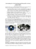
1 Mounting of Optical ComponentsMounting of lensesJim BurgeProfessor, Optical Sciences and AstronomyUniversity of ArizonaTucson, AZ 2011J. H. Burge2 Design approach for lens mounts Lenses are axisymmetric, usually with spherical surfaces Key drivers for design are centration and spacing tolerances Metal barrels can be machined so they are highly symmetric1. Place one lens spherical surface onto a true surface on the barrel. This gives excellent accuracy at low Remaining degree of freedom is centration. Control by size of bore, lens, and tight tolerance, clamped or potted in place direct centering error lens wedge Lens barrel is critical for control of stray light Balance with Optical design to maintain clear aperture, but limit strays Blacken edges of lenses that are illuminated or are viewed Cut threads on inside surfaces, blacken for good rejection Avoid specular reflections into the sensor, even from blackened surfaces Add baffle tube in front of lensesJ.
2 H. Burge3 Using Surface Contact can help to accurately locate the optic correctlyMount lenses using the Optical surfaceFig. Registering a poorly edged lens by its rim may result in tilt or decentration of the Optical axis (b) decenter (c) tilt (d) tilt and decenterJ. H. Burge4 Mechanical surface can be in the wrong place with no negative consequencesLens mounts: align the opticalsurfacesJ. H. Burge5 Locating the Lens with an axial preload can help to hold a lens in place against maximum acceleration as for lens mountsFigure Yoder, Mounting Optics In Optical Instruments 2ndEd. J.
3 H. Burge6 Lens seatsJ. H. Burge7 Basic Type of Lens Seats: Sharp Corner (R ~ or 50 m) toroidal Lens Seat Conical or Tangential Seat Spherical Lens Seat Flat Lens Seat Sharp Corner Interfaces for Concave and Convex SurfacesLens interfaces: the sharp cornerFigure Figure Yoder, Mounting Optics In Optical Instruments 2ndEd. J. H. Burge8 Issues with the sharp corner Provides highest accuracy, and is easy to verify Potentially large contact stresses For most applications, these will not cause any risk Sharp corners are susceptible to damage or to burrs Standard practice of breaking corners will result in loss of accuracy Sharp corner with radius > can be considered as toroidal seatREFERENCE SURFACE dseatzseatzvertexzsag(r)J.
4 H. Burge9 Tensile stress, caused by contact stress The deformation due to point loading on a glass surface causes a localized tensile stress at the surface, a small distance from the load. The peak tensile stress Tis estimated as C is the peak compressive stress from the concentrated load is Poisson s ratio for the glass This stress field is small, and shallow This can be a concern for point loads, which can cause a conical fracture in the glass The effect for line loads does not drive most designs Verified by testing at UA. Unable to detect decreased strength, even after loading with >50,000 psiFinite element model of cylinder on flatR = 2 , 9 lb/in loadwith < elements3800 psi maximum compressive stress350 psi maximum tensile from the load< deep CT 321 Compressive stressTensile stressGeometry for toroidal seats for lens mountsrRz 22 rRRzIf sharp corner is defined, but actual radius of is obtained, axial shift of lens, with respect to ideal, is Rrz Position of lens vertexdefined by toroidal interfaceToroidal interface.
5 Radius position defined by intersection of flat and cylindrical surfacesTypical value for is mm or Specifying toroidal interfaceJ. H. Burge12 Reduce contact stress using conical interface Note that this works only for convex surfaces It is harder to hold the lens spacing tolerances with conical seatsConical interface, or tangent contactFig Yoder, Mounting Optics In Optical Instruments 2ndEd. Geometry for conical interface, or tangent contactPosition of lens vertexdefined by conical interfaceChoose OD for mechanical clearance of lens in barrel Choose ID for Optical clear aperture = cone anglerb= radius of barrel datum cylinderrt= contact radius of cone and spherical surfacez= position of lens vertex with respect to intersection of conical seat and barrel datum cylinderRrt sin tancos11brRz z GD&T for conical lens seatJ.
6 H. Burge15 Very benign, nominally zero stress concentration Difficult to manufacture and measure accurately. Possible, but costs will be driven significantly by these interface types. Seldom justifiedSpherical SeatsFigure Yoder, Mounting Optics In Optical Instruments 2ndEd. J. H. Burge16 Edge Flat Seat and Various surfaces can be used for a lens Mounting purposes. Any Mounting surfaces should be treated as precisely defined and oriented surfaces Uncertainty in cutting the Mounting surface will directly affect lens position accuracyUsing mechanical surfaces for Mounting interfaces Figure Figure Yoder, Mounting Optics In Optical Instruments 2ndEd.
7 J. H. Burge17 Retainers The features in the lens barrels should define the lens position The retainers maintain a preload to hold the lens in place Types of retainers: Burnished Edge Flexure Snap Ring Threaded Retainer Press Fit or Interference Fit Retainer Elastomeric RetainerJ. H. Burge18 The metal of the lens cell is either rolled or bent into the appropriate shape to hold the lens in place. Preloads and springs may be used as well Low cost for productionLens retainer with burnished edgeFigure Yoder, Mounting Optics In Optical Instruments 2ndEd. J. H. Burge19 For larger lenses compliant spacers can be used under the Mounting screws to help to distribute force more evenly around the optic being mountedProvides good control of compliant preloadIncrease part count and costLens retainer with flexure ringJ.
8 H. Burge20 Low cost, simple design Common practice uses a ring with circular cross section. Once in place, virtually impossible to get outLens retainer with snap ringFigure Figure Yoder, Mounting Optics In Optical Instruments 2ndEd. J. H. Burge21 Easy design, easy to make Allows easy assembly and disassemblyLens retainer using threaded ringFigure Figure Yoder, Mounting Optics In Optical Instruments 2ndEd. J. H. Burge22 Torque setting for retaining ringsPFigure Yoder, Mounting Optics In Optical Instruments 2ndEd. J. H. Burge23 Easy design, low cost production Difficult to control preload Difficult or impossible to disassembleLens retainer ring pressed inFig.
9 Yoder, Mounting Optics In Optical Instruments 2ndEd. J. H. Burge24 Pot the lens in place Need to provide holes to inject adhesive Control adhesive flow during assembly. Don t get it on the Optical surfaceFigure Yoder, Mounting Optics In Optical Instruments 2ndEd. J. H. Burge25 System assemblies : Barrels Barrels are usually aluminum, easy to machine Stainless steel (416) gives better CTE match, can go to thinner sections Simplest barrel is a straight bore. All lenses are the same size. Low cost, high accuracy More complex barrels are needed for most Optical designs Set machining tolerances to allow simple assembly.
10 Maintain radial clearance for assembly This will also limit interference from thermal effects Readily achieve accuracy of 50 m. Work harder and get to 25 m For higher accuracy with this type of design Provide centration adjustment based on rotation measurement, then pot lens Provide spacing adjustment using shimsFigure Yoder, Mounting Optics In Optical Instruments 2ndEd. Easiest lens barrelLenses of Equal Diameter With Axial Position Defined by Spacers Precise bore is low cost operation Assembly is easy Rely on tolerances of lenses for centration Rely on tolerance of spacers for tilt, axial spacingJ.