Transcription of MULTISIM TUTORIAL - Michigan Technological University
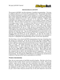
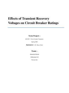
1 MULTISIM TUTORIAL Start Click on Start All Programs National Instruments Circuit Design Suite MULTISIM . 1. Open/Create Schematic A blank schematic Circuit 1 is automatically created. To create a new schematic click on File New Schematic Capture. To save the schematic click on File /Save As. To open an existing file click on File/ Open in the toolbar. 2. Place Components To Place Components click on Place/Components. On the Select Component Window click on Group to select the components needed for the circuit. Click OK to place the component on the schematic. Instrument Toolbar Component Toolbar Virtual Component Toolbar Ammeter/ Voltmeter Toolbar Simulation Toolbar Place Your Circuit Here Figure 1: Select Resistor Figure 2: Select DC voltage For example to select resistors and the DC source shown in Figure 3 click on Place/ Components. In Group select Basic scroll down to Resistors and select the value of the resistor needed to construct the circuit, for this example select 1k.
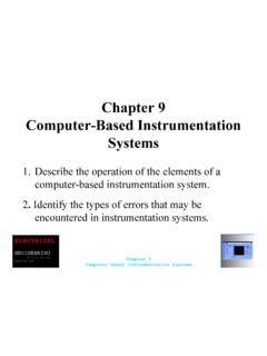
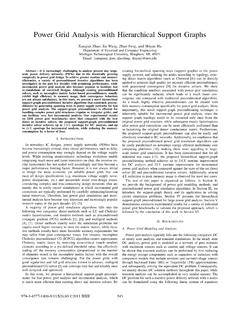
2 To place DC source click on Sources in Group and select DC Source. As shown in Figure 1 and Figure 2 respectively. Figure 3: DC Source & Resistors Virtual Components Components can also be place on the circuit using Virtual components. Click on View Toolbars and select the toolbar needed for the circuit. Figure 4: Virtual Components 4. Rotate Components To rotate the components right click on the Resistor to flip the component on 90 Clockwise (Ctrl +R) and 90 Counter Clockwise (Ctrl+Shift+R). Figure 5: Rotate Components 5. Place Wire/Connect Components To connect resistors click on Place/Wire drag and place the wire. Components can also be connected by clicking the mouse over the terminal edge of one component and dragging to the edge of another component. Reference Figure 6.
3 Figure 6: Place/ Wire 6. Change Component Values To change component values double click on the component this brings up a window that display the properties of the component. Reference Figure 7. Change R1 from 1k Ohm to 10 Ohms, R2 to 20 Ohms, R3 to 30 Ohms, and R4 to 40 Ohms. Also change the DV source from 0 V to 20 V. Figure 8 shows the completed circuit Figure 7: Change Component Values Figure 8: Completed Circuits 7. Grounding: All circuits must be grounded before the circuit can be simulated. Click on Ground in the toolbar to ground the circuit. If the circuit is not grounded MULTISIM will not run the simulation. Figure 9: Grounding 8. Simulation: To simulate the completed circuit Click on Simulate/Run or F5. This feature can also be accessed from the toolbar as shown in the Figure 10 below. Figure 10: Simulation Ground RUN PAUSE STOP Analyzing Components MULTISIM offers multiple ways to analyze the circuit using virtual instruments.
4 Some of the basic instruments needed for this lab are described below. 1) Multimeter Use the Multimeter to measure AC or DC voltage or current, and resistance or decibel loss between two nodes in a circuit. To use the Multimeter click on the Multimeter button in the Instruments toolbar and click to place its icon on the workspace. Double-click on the icon to open the instrument face, which is used to enter settings and view measurements. Figure 11: Multimeter To measure Voltage place multimeter in Parallel with the component (Resistor, Voltage etc). To measure Current place the multimeter in series with the component. Reference the Figure 12 and 13. Figure 12: Measure Voltage Figure 13: Measure Current 2) Wattmeter The wattmeter measures power. It is used to measure the magnitude of the active power, that is, the product of the voltage difference and the current flowing through the current terminals in a circuit.
5 Figure 14: Wattmeter To use the instrument, click on the Wattmeter button in the Instruments toolbar and click to place its icon on the workspace. The icon is used to wire the Wattmeter to the circuit. Double-click on the icon to open the instrument face, which is used to enter settings and view measurements. Reference Figure 15 for more details. Figure 15: Wattmeter Connection Insert in series with the Load Connect in Parallel with the Load 3) Agilent Multimeter 1. The Agilent Mulitmeter Instrument can also be used to measure and simulate circuits with more accuracy. To use the multimeter click on the Agilent Multimeter tool button, place its icon on the workspace and double-click on the icon to open the instrument. Click on the Power button to switch on the instrument. For more information Reference MULTISIM Instruction Figure16: Agilent Multimeter.
6 4) Ammeter: The ammeter offers advantages over the multimeter for measuring current in a circuit. It takes up less space in a circuit and you can rotate its terminals to suit your layout. Always connect the ammeter in series with the load. To place Ammeter click on View--- Toolbar --- Select Measurement Components. See Figure 17 on how to use the Ammeter. Figure 17: Ammeter 5) Voltmeter The Voltmeter offers advantages over the multimeter for measuring voltage in a circuit. Always connect the voltmeter in parallel with the load. The voltmeter can be found in the measurement toolbar. Figure 18: Voltmeter Note: This TUTORIAL offers an introduction to MULTISIM which includes description and examples on how to use basic instruments needed for EE3010 labs. For more information on instruments not described in this TUTORIAL please reference MULTISIM INSTRUCTION for detailed descriptions. Ammeter Voltmeter