Transcription of MX-100 SERIES MIXING STATIONS - KnightEquip.com
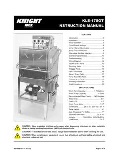
1 Page 1 of 6 0900936 Rev C 05/01 ,167$//$7,21 mounting THE UNIT (1) Choose a convenient location close to water supply and not more than 5 off floor. (2) Remove the cover from the unit. (3) Hold proportioner against wall and mark keyholes use a level for marking holes. (4) Drill holes and install either toggle bolts or masonry screws (not supplied). (5) Hang the unit and tighten screws see Figures 1 and 2. Always refer to hardware manufacturer s specifications for weight capacity and usage. ATTACHING THE DRIP TRAY (OPTIONAL) (1) Locate tray 12 to 15 below spouts. Mount in the same manner as proportioner. (2) Attach a length of 1/4" tubing to drip tray for draining liquids. (3) Divert drain tube to sink, drain, or five gallon holding jug. CONNECTING THE WATER SUPPLY This proportioner operates best with a flowing water pressure of 30 - 40 PSI.
2 Fluctuating pressure can affect dilution ratios use a water source that is not feeding other equipment whenever possible. Water temperature should be between 40 F and 180 F. (1) Attach male connector on high pressure supply hose to inlet side of proportioner using garden hose washer. (2) Attach female connector on high pressure hose to water source. (3) Turn on water and check for possible leaks. IMPORTANT NOTE: If proportioner is connected to a janitor s sink with an atmospheric vacuum breaker, a special connection kit is required by specification 1055. Failure to use this kit, or equivalent connection means, will invalidate the and (UPC) certification. Specify P/N 7600187 when ordering the kit. MX-100 SERIES MIXING STATIONS FOR DRYWALL SURFACE WASHER TOGGLE BOLT SIDE VIEW Figure 1 FOR CINDER BLOCK & CONCRETE SIDE VIEW MASONRY SCREW Figure 2 0900936 Rev C 05/01) Page 2 of 6 &+226,1* 7+( )/2: 5$7( STANDARD VENTURI AND FLEX-GAP For standard venturi and Flex-Gap systems, the flow rate is controlled by a venturi tube located within the venturi body.
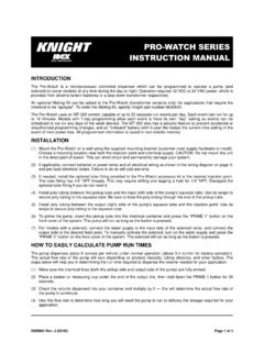
3 Venturi tubes have their GPM rating molded on the side, or can be identified by color; WHITE = 1 GPM/ BLACK = 4 GPM. To change the venturi tube: (1) Disconnect tubing from venturi body. (2) Remove venturi body. (3) Push out existing venturi tube by inserting a pen up through the bottom of the venturi body see Figure 3. (4) Insert the new venturi tube (for the desired flow rate) into the venturi body, ensuring that it seats firmly. (5) Thread venturi body back in place and hand-tighten. AIRE-GAP VENTURI For Aire-Gap venturi systems, the flow rate is controlled by a nozzle, deflector plate, and venturi tube. These internal parts are color coded to identify their GPM rating; BLUE = 1 GPM/BLACK = 3 GPM. To change these parts: (1) Disconnect tubing from venturi body. (2) Remove Aire-Gap assembly from water valve.
4 (3) Remove existing nozzle, deflector plate, and venturi tube by disassembling the Aire-Gap see Figure 4. (4) Reassemble the Aire-Gap using new nozzle, deflector plate, and venturi tube (for the desired flow rate). To avoid leakage, install the rubber washer with the 3 ears facing upwards. Hand-tighten the venturi body to the Aire-Gap body. (5) Thread Aire-Gap assembly back in place and hand-tighten. &+226,1* ',/87,21 5$7(6 IMPORTANT: The dilution chart for the standard venturi and Flex-Gap is different than the chart for the Aire-Gap venturi. Be sure to use the correct dilution chart for metering tip selection. METERING TIP SELECTION For each valve in the system, install appropriate metering tip from the charts on page 3. Be sure the metering tip is threaded in hand-tight only.)
5 CALIBRATING ACTUAL PRODUCT RATIOS To easily calculate the ounces per gallon for a specific product: (1) Fill a graduated cylinder or spray bottle (that has ounce markings) with product. (2) Install metering tip closest to desired ounces per gallon see dilution charts. (3) Drop chemical pick-up tube into the container holding the product. (4) Activate valve until chemical line is primed up to the metering tip. (5) Note how many ounces (of product) are in the container. (6) Activate valve again, and fill a one gallon container with water/product mix. (7) Note how many ounces (of product) were used. (8) You now have determined actual ounces per gallon for this product. Repeat this procedure as desired for other valves and products. SCREEN WASHER 2300812 NOZZLE SCREENS (2) 7407211 NOZZLE 1 GPM = 7407201 3 GPM = 7407202 AIRE-GAP BODY 7407200 DEFLECTOR PLATE 1 GPM = 7407220 3 GPM = 7407221 RUBBER WASHER 2300781 AIRE-GAP VENTURI TUBE 1 GPM = 7407204 3 GPM = 7407205 O-RING 1500477 AIRE-GAP VENTURI BODY 7407203 DE-FOAM TUBE 7025903 Figure 4 Figure 3 VENTURI BODY VENTURI TUBE PEN Page 3 of 6 0900936 Rev C 05/01 These charts are based upon the chemical viscosity of water (CPS = ) and should only be used as a guide.
6 Actual ratios and flow rates may vary due to product viscosity, flow pressure, and tubing distance(s). 23(5$7,21 CONNECTING THE CHEMICAL SUPPLY IMPORTANT: When an Aire-Gap venturi is operating without a chemical supply line connected, or a supply line that is not completely full, water may spit from the gap area. The spitting is considered normal and will cease when the supply line is filled with chemical. This does not apply to standard venturi or Flex-Gap. (1) Locate chemical container(s) below the proportioner. (2) Insert the foot-valve end of the 3/8" vinyl tube into each container (use ceramic weight if necessary to sink tube to bottom). (3) Connect the inlet tube over the colored metering tip secure with a plastic zip tie. INSTALLING BUCKET-FILL TUBE (OPTIONAL) (1) Remove spring clip securing the unused spout in place.)
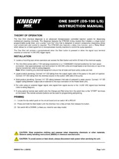
7 (2) Remove spout and cover remaining hole with plastic plug provided. (3) FOR STANDARD VENTURI AND FLEX-GAP: Connect the bucket fill tube with the flow restrictor (plastic insert) end closest to the venturi body. FOR AIRE-GAP VENTURI: Connect a fill tube with no flow restrictor (plastic insert) or cut the restrictor off the end of an existing tube. (4) Secure tube to venturi body with tie wraps provided. (5) Route the other end out through the bottom of the case. (6) When not in use, hang the tube on the drip tray (optional) using the hook provided. INSTALLING BUTTON LOCK TAB (OPTIONAL) See Figure 5 for illustration. (1) Install button lock tab (provided) between the magnet stem and magnet screw. (2) Ensure that tab is pointing up and down as magnet screw is tightened. (3) Cut off tab in the slot of locking button.
8 (4) Rotate button as cover is placed back on unit to line up the slot with the tab. (5) Button will now lock in the on position by turning slightly clockwise while pressed in. (6) Turn button counter-clockwise to release. AIRE-GAP VENTURI 1 GPM TIP COLOR OZ/GAL RATIO OZ/GAL RATIO NO INSERT 35 :1 21 :1 WHITE 32 :1 20 :1 YELLOW 30 :1 18 :1 PINK 26 :1 16 :1 GREEN 23 :1 12 10:1 BLACK 20 :1 10 12:1 BROWN 16 :1 7 17:1 GRAY 10 12:1 5 25:1 BLUE 7 17:1 4 31:1 RED 4 31:1 3 42:1 PEACH 50:1 2 63:1 LT BLUE 56:1 84:1 PURPLE 2 63:1 1 127:1 LT GREEN 84:1 170:1 ORANGE 1 127:1 255:1 LT BROWN 255:1 511:1 3 GPM STANDARD VENTURI/FLEX-GAP 1 GPM TIP COLOR OZ/GAL RATIO OZ/GAL RATIO NO INSERT 28 :1 25 :1 WHITE 22 :1 20 :1 YELLOW 18 :1 18 :1 PINK 16 :1 16 :1 GREEN 15 :1 12 12:1 BLACK 14 :1 10 15:1 BROWN 12 10:1 7 20:1 GRAY 8 15:1 5 31:1 BLUE 6 20:1 4 42:1 RED 3 42:1 3 63:1 PEACH 50:1 2 72:1 LT BLUE 63:1 101:1 PURPLE 74:1 1 127:1 LT GREEN 84:1 170:1 ORANGE 1 127.
9 1 255:1 LT BROWN 255:1 511:1 4 GPM 0900936 Rev C 05/01) Page 4 of 6 6$)(7< $1' 6(59,&,1* 7,36 Avoid direct contact with chemicals handle containers with caution. To avoid spillage, be careful not to tip containers. Insert chemical suction line into container so that footvalve and ceramic weight sink to the bottom. If valve fails to draw chemical, check the metering tip and footvalve for blockage soak in warm water to clear. ',6&/$,0(5 Knight Inc. does not accept responsibility for the mishandling, misuse, or non-performance of the described items when used for purposes other than those specified in the instructions. For hazardous materials information consult label, MSDS, or Knight Inc. :$55$17< All Knight controls and pump systems are warranted against defects in material and workmanship for a period of ONE year.)
10 All electronic control boards have a TWO year warranty. Warranty applies only to the replacement or repair of such parts when returned to factory with a Knight Return Authorization (KRA) number, freight prepaid, and found to be defective upon factory authorized inspection. Bearings and pump seals or rubber and synthetic rubber parts such as O rings, diaphragms, squeeze tubing, and gaskets are considered expendable and are not covered under warranty. Warranty does not cover liability resulting from performance of this equipment nor the labor to replace this equipment. Product abuse or misuse voids warranty. MAGNET WITHOUT TAB TAB MAGNET MAGNET WITH TAB BUTTON LOCK TAB MAGNET SCREW ARMATURE GUIDE STEM POINT UP AND DOWN Figure 5 World Headquarters: 20531 Crescent Bay Dr. Lake Forest, CA 92630-8825 USA TEL: (949) 595-4800 FAX: (949) 595-4801 Atlanta Branch: 8111 Technology Dr.