Transcription of NCMA TEK
1 Sized to provide sufficient design strength. Further informa-tion on determining design loads for lintels is included inAllowable Stress Design of Concrete Masonry Lintels, TEK17-1A (ref. 3).Nominal lintel strength is determined based on thestrength design provisions of ACI 318 and then reduced bystrength reduction factors, called phi ( ) factors. Thesefactors account for any variability in materials and construc-tion practices. The resulting capacity needs to equal or exceedthe factored loads. Precast concrete strength reduction factorsare and for flexure and shear, respectively (ref. 2).
2 Tables 1 through 4 list design moment and shear strengthsfor various precast lintel sizes and concrete strengths, basedon the following criteria (ref. 2).Flexural strength: Mn= [As fy(d-a/2)], = strength, no shear reinforcement: Vn= (2) (f 'c)1/2 bd, = 318 contains requirements for minimum and maxi-mum reinforcing steel areas to ensure a minimum level ofperformance. Minimum reinforcement area for lintels is As min= 3(f'c)1/2bd/fy but not less than 200bd/fy. In addition, thereinforcement ratio is limited to 75% of the balanced rein-forcement ratio, max = : flexural strength, lintels, strength design, struc-tural propertiesINTRODUCTIONL intels function as beams to support the wall weight andother loads over an opening, and to transfer these loads to theadjacent masonry.
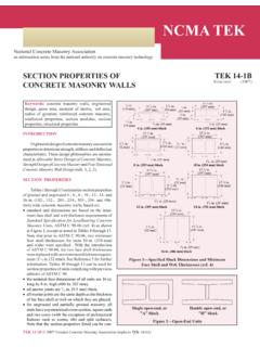
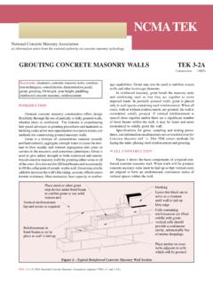
3 Because of their rigidity, strength, durability,fire resistance and aesthetics, the most common types of lintelsfor concrete masonry construction are those manufactured ofprecast reinforced concrete or reinforced concrete masonryunits (ref. 3). The color and surface texture of these lintels canbe used as an accent or to duplicate the surrounding DIMENSIONSP recast lintel dimensions are illustrated in Figure concrete lintels are manufactured to modular sizes,having specified dimensions corresponding to the concretemasonry units being used in the modular lintel length should be specified, with a mini-mum length of the clear span plus 8 in.
4 (203 mm), to provide atleast 4 in. (102 mm) bearing at each end (ref. 1). Additionally,if lintels are subjected to tensile stresses during storage, trans-portation, handling, or placement, it is recommended that steelreinforcement be provided in both the top and bottom to preventcracking. Minimum concrete cover over the steel should be11/2 in. (13 mm). The lintel width, or width of the combinationof side-by-side lintels, should equal the width of the supportedmasonry should be clearly marked on the top wheneverpossible to prevent the possibility of improper installation inthe wall. In the event the top of the lintel is not marked andmay be installed upside down, the same size bars should beused in both the top and DESIGNP recast concrete lintels are designed using the strengthdesign provisions of Building Code Requirements for Struc-tural Concrete, ACI 318-99 (ref.)
5 2). In strength design,service loads are increased to account for variations inanticipated loads, becoming factored loads. The lintel is thenPRECAST CONCRETE LINTELS FORCONCRETE MASONRY CONSTRUCTION tek 17 -2 AStructural (2000) ncma TEKNCMA TEKN ational Concrete Masonry Associationan information series from the national authority on concrete masonry technologyTEK 17-2A 2000 National Concrete Masonry Association (replaces tek 17 -2)Figure 1 - Precast Lintel Design ParametersDeflection criteria for lintels is based on controlling crack-ing in the masonry being supported. Consequently, less deflec-tion is allowed when the lintel supports unreinforced this case, lintel deflection is limited to the effective span of thelintel (measured in inches) divided by 600 (L/600) (ref.
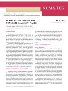
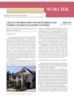
6 1). Inaddition, ACI 318 limits precast lintel deflection to L/240 whenthe element supported by the lintel is not likely to be damagedby large deflections, and L/480 when the element supported bythe lintel is likely to be damaged by large deflections. Linteldeflection is calculated based on the effective moment of inertia,Ie, as follows (ref. 2, Section ).Ie= (Mcr/Mmax uf )3Ig + [1- (Mcr/Mmax uf )3]Icr < IgShrinkage and creep due to sustained loads cause addi-tional long-term deflections over and above those occurringwhen loads are first applied. ACI 318 requires that deflectionsdue to shrinkage and creep are included, and provides anexpression to estimate this additional deflection (ACI 318 Section ): = /(1+50 ')where = for exposures of 5 years or EXAMPLEThe residential basement wall shown in Figure 3 needsa lintel over the window opening.
7 The floor live load is 400lb ( kN) per joist and the floor dead load is 100 lb ( kN)per joist. Consider the floor joist loads, spaced at 16 in. (406mm) on center, as uniformly distributed. Use a lintel self-weight of 61 lb/ft ( kN/m) and weight of lb/ft2 ( ) for the bond beam at the top of the wall over the lintel(ref. 4).Determine effective depth, d: Assuming an 8 in. (203 mm)high lintel with two No. 4 (13M) bars,d= in. - in. - in. (149 mm)Check for arching action: The effective span length, L = 96+ = in. (2588 mm). Since the height of masonryabove the opening is less than L/2, arching of the masonryover the opening cannot be assumed (see ref.)
8 4 for detailedinformation about determining arching action).Determine design loads:LL= (400 lb)(12/16 in.)= 300 lb/ft ( kN/m)Dead loads include floor, wall, and lintel 100 lb (12/16 in.)= 75 lb/ft ( kN/m)Dlintel= 61 lb/ft ( kN/m)Db beam= ( )( ft)= 50 lb/ft ( kN/m)Dtotal= (75 + 61 + 50)= 186 lb/ft ( kN/m)For deflection calculations use loads as given above. Forstrength design multiply live loads by and dead loads by moment and shear for strength design:Mmax =wL2/8= {[( )(300)+( )( 186 ) lb/ft]( in.)2/8}(ft/12 in.)= 83,328 ( )Vmax=wL/2 (at distance "d" from support) ( )= [( )(300)+( )(186 lb/ft)]( in.
9 (ft/12 in.)= 2,893 lb ( kN)From Table 3, an 8 x 8 in. (203 x 203 mm) lintel with two (13M) bars and f 'c = 4000 psi ( MPa) has deflection: Deflection is determined using the effectivemoment of inertia of the lintel, Ie, calculated as follows (ref. 2).Ec= (f'c)1/2= (150 pcf) (4000 psi)1/2= 3,834,000 psi (26,400 MPa)fr= (f'c)1/2= 474 psi ( MPa)yt= in. (97 mm)Ig=bh3/12= ( in.)( in.)3/12= 282 (11,725 cm4)Mcr=frIg/yt= 474 psi(282 psi) 35,083 ( )Mmax uf=wL2/8 = [(300+186 lb/ft)( in.)2/8](ft/12 in.)= 52567 ( )(Mcr/Mmax uf )3 = (35,083/52567)3 = = 29,000,000/3,834,000 = =As /bd = ( in.)
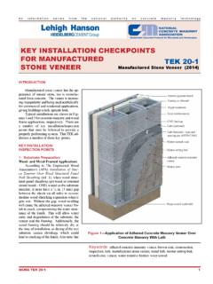
10 ( in.) = = ( ) = d[(1 + 2/n )1/2 - 1]= ( in.)[(1+ 2 )1/2-1] = in. (45 mm)Figure 2 - Strength Design Structural ModelFigure 3 - Wall Configuration for Design Example Table 1 - Shear and Moment Capacity for 4 x 8 in. (102 x 203 mm) Reinforced Concrete LintelsReinforcing 'c, psi (MPa)bar sizeof3000 ( )3500 ( )4000 ( )(No.)bars Vn Mn Vn Mn Vn Mnlb (kN) ( )lb (kN) ( )lb (kN) ( )3 (10M)12,000 ( )33,140 ( )2,160 ( )33,450 ( )2,310 ( )33,670 ( )4 (13M)11,980 ( )56,440 ( )2,140 ( )57,440 ( )2,290 ( )58,190 ( )5 (16M)11,960 ( )80,450 ( )2,110 ( )82,860 ( )2,260 ( )84,670 ( ) Table 2 - Shear and Moment Capacity for 6 x 8 in.