Transcription of NCMA TEK
1 NCMA TEK. National Concrete Masonry Association an information series from the national authority on concrete masonry technology FLOOR AND ROOF CONNECTIONS TO TEK 5-7A. Details (2001). CONCRETE MASONRY WALLS. Keywords: connections, floor systems, hollowcore, floor system. Hangers are generally anchored to a wall joists, ledger, loadbearing concrete masonry, pocket, through a joint and into a bond beam. However, hangers roof systems, trusses approved for direct attachment to the surface of a masonry wall are also available. Ledger Connection As with hangers, ledger connec- INTRODUCTION. tions minimize the impact on the continuity of a masonry wall. A ledger connection reduces the necessary pre-plan- Floor and roof systems for use with loadbearing struc- ning and does not unduly impact the mason's work as opposed tural concrete masonry walls serve three primary functions: to a pocket connection; thereby reducing the number of field they transmit the vertical dead load and live load to the bearing modifications.
2 Walls; they function as diaphragms, transmitting lateral wind Note: Most of the connections herein depict flashing for and seismic loading through the walls to the foundation; and water penetration resistance which should be used in all exterior they act to support the walls from out-of-plane loads. In walls. Normally flashing is not provided in interior walls. addition to these structural functions, floors and roofs should provide a satisfactory barrier to the transmission of sound, FLOOR AND ROOFING SYSTEMS. fire, and heat. The many types of floor and roof systems in use today are designed to satisfy all of these requirements in an Several materials are common to roof and floor con- economical manner. struction.
3 Wood, concrete, and steel are among the most frequently used framing materials in these applications. CONNECTIONS. Wood Systems The transfer of loads between diaphragms and walls Wood framed floors and roofs are common in residen- requires the proper design and detailing of the connection tial and low-rise construction. It is imperative when con- linking these elements. Connections critical to the integrity structing a wood-framed system that it not be in direct of a structure. The connections detailed herein address contact with the concrete masonry. Wood in contact with minimal requirements. Additional requirements may be masonry materials may absorb moisture present in the con- necessary in some locals, particularly where earthquake and crete masonry causing the wood to rot.
4 To prevent the high wind forces are to be resisted. The four primary types of resulting unwanted decay, the lumber used should be pres- connections, each having specific advantages, include: sure-treated, naturally decay resistant, or have a moisture Direct Bearing Connection The direct bearing connec- barrier placed between the wood and the concrete masonry. tion is often the simplest type of connection. This connec- tion is used at the top of concrete masonry walls or when a Steel Systems change in wall thickness provides a ledge with sufficient Steel-framed roofs using steel bar joints are very com- bearing area as shown in Figure 1. mon in commercial structures because they are capable of Pocket Connection A pocket connection consists of spanning long distances.
5 Steel bar joists typically use pock- framing the floor or roof system into a void in the masonry eted or ledger connections to concrete masonry walls. Pro- wall. This detail is used when masonry continues above prietary systems that use concrete masonry units as a filler (either as part of the wall or as a parapet) the connection between the steel joists are also available. location and eccentricity is to be minimized. Care must be taken to insure that the use of a pocket does not interfere with Concrete Systems the continuity of the vertical reinforcement in the wall. Concrete slabs can take many forms, including pre- Hanger Connection When it is desired to maintain the stressed, precast, and cast-in-place construction.
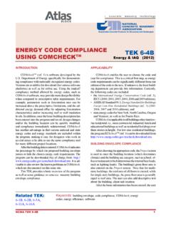
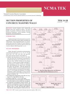
6 Depending continuity of the wall for structural, aesthetic, or construc- upon the size and number of stories associated with a given tion reasons, a wall hanger can be used to suspend the roof or TEK 5-7A 2001 National Concrete Masonry Association (replaces TEK 5-7 and TEK 17-5 ). Superstructure Blocking or band joist Toenail or tie as required Solid or filled masonry unit to support flashing Wood joist Stop flashing at Cavity fill or inside of faceshell other mortar Void/pocket Sill (pressure treated collection device Fire-cut end of joist or provide moisture barrier) (as required). Anchorage as required 1 in. (25 mm) Sheathing partially open "L" shaped head Reinforced bond beam joints for weeps Concrete masonry wall at 32 in.
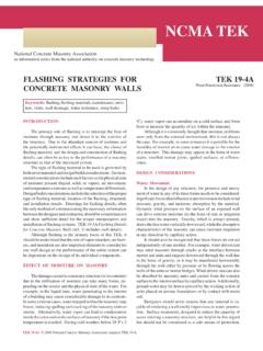
7 (814 mm). Drip edge Wood joist Figure 1 Direct Bearing Wood Floor Joist (ref. 2) Pressure treated or provide moisture barrier Reinforcement Stop flashing at inside Cavity fill or other mortar of faceshell Grout stop Concrete masonry bond beam collection device Provide gap or moisture barrier as required Blocking or band joist Figure 5 Wood Floor Joist With Pocket 1 in. (25 mm) partially Sheathing open "L" shaped head Wood joist joints for weeps Toe nail or tie at 32 in. (814 mm) as required Drip edge Sill (pressure treated or provide moisture barrier) 2 in. (51 mm) deep Cavity fill or other Solid or filled 4 in. (102 mm) unit Anchorage as required unit to support mortar collection device flashing (solid or filled) to Reinforced bond beam Reinforced support flashing 1 in.
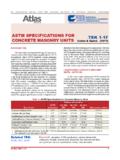
8 (25 mm) partially open "L" shaped head bond beam Concrete masonry wall Ledger joints for weeps at 32 in. (814 mm). Sheathing Figure 2 Direct Bearing Wood Floor Joist Drip edge Stop flashing at Grout stop Cavity fill or other mortar inside of faceshell Wood joist collection device Joist hanger; fasten as required by Joist hanger 1 in. (25 mm) partially hanger manufacturer open "L" shaped head Double (shown) or Sheathing staggered anchor joints for weeps bolt as required Drip edge Wood joist 4 in. (102 mm) unit Reinforced Figure 6 Wood Ledger and Hanger (solid or filled) to bond beam support flashing Figure 3 Wood Floor Joist Hanger (ref. 2). Concrete masonry wall Stop flashing at Stop flashing at inside of faceshell inside of faceshell Cavity fill or Cavity fill or other mortar 4 in.
9 (102 mm) unit (solid or Provide gap or moisture filled) to support flashing other mortar barrier as required collection device collection device Notch/pocket 1 in. (25 mm) Wood truss 1 in. (25 mm). partially open partially open "L" shaped head joints for weeps "L" shaped head at 32 in. (814 mm) joints for weeps at 32 in. (814 mm). Wood Truss Drip edge Bearing truss hanger; Drip edge Reinforcement fasten as required by hanger Concrete manufacturer Bond beam masonry wall Reinforced bond beam Figure 4 Wood Floor Truss Hanger (ref. 2) Figure 7 Wood Floor Truss Pocket (ref. 2). Sloping sheet metal coping cap with cont. cleat. each side Grout cores solid at anchor bolts Wood Nailer with anchor bolts Attachment strip Cavity fill or other mortar collection device Counter flashing Standard unit with Sealant inside faceshell and part of web removed Stop flashing at inside of Sill (pressure treated or faceshell (see TEK 19-2A).)
10 Provide moisture barrier) 1 in. (25 mm) partially Toenail per open "L" shaped head Cant code or use Anchor bolt or joints for weeps Parapet flashing rated connector specialty anchor at 32 in. (814 mm) Sealant as required Drip edge Roofing membrane Bond beam Concrete masonry wall Solid unit notched around joist steel plate with anchor Figure 8 Wood Roof Truss with Top Plate (ref. 2) Grout stop Reinforced bond beam Masonry wall Steel bar joist welded or bolted to bearing plate Figure 11 Steel Joist with Pocket (ref. 3, 4, 5). +. +. +. +. o o o Moisture barrier Uplift connector as required Reinforced bond beam Concrete masonry wall Isolation joint 1 in. (25 mm) partially Steel bar joist welded or Figure 9 Wood Roof Truss with Embedded open "L" shaped head bolted to ledger angle Strap Anchor (ref.