Transcription of NI 6221 68-Pin Device Specifications - National Instruments
1 Device SPECIFICATIONSNI 6221M Series Data Acquisition: 16-Bit, 250 kS/s, 16 AI, 24 DIO, 2 AOThe following Specifications are typical at 25 C, unless otherwise noted. For moreinformation about the NI 6221, refer to the M Series User Manual available at InputNumber of channels8 differential or 16 single endedADC resolution16 bitsDNLNo missing codes guaranteedINLR efer to the AI Absolute Accuracy sectionSample rateSingle channel maximum250 kS/sMultichannel maximum (aggregate)250 kS/sMinimumNo minimumTiming accuracy50 ppm of sample rateTiming resolution50 nsInput couplingDCInput range V, 1 V, 5 V, 10 VMaximum working voltage for analoginputs (signal + common mode) 11 V of AI GNDCMRR (DC to 60 Hz)92 dBInput impedanceDevice onAI+ to AI GND>10 G in parallel with 100 pFAI- to AI GND>10 G in parallel with 100 pFDevice offAI+ to AI GND820 AI- to AI GND820 Input bias current 100 pACrosstalk (at 100 kHz)Adjacent channels-75 dBNon-adjacent channels-90 dBSmall signal bandwidth (-3 dB)
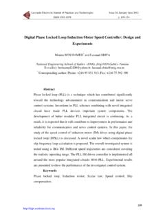
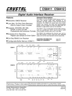
2 700 kHzInput FIFO size4,095 samplesScan list memory4,095 entriesData TransfersPCI/PXIDMA (scatter-gather), interrupts,programmed I/OUSBUSB Signal Stream, programmed I/OOvervoltage protection for all analog input and sense channelsDevice on 25 V for up to two AI pinsDevice off 15 V for up to two AI pinsInput current during overvoltage condition 20 mA maximum/AI pinSettling Time for Multichannel MeasurementsAccuracy, full-scale step, all ranges 90 ppm of step ( 6 LSB)4 s convert interval 30 ppm of step ( 2 LSB)5 s convert interval 15 ppm of step ( 1 LSB)7 s convert interval2 | | NI 6221 Device SpecificationsTypical Performance GraphsFigure 1. Settling Error versus Time for Different Source Impedances1101001 k10 k1101001 k 2 k 5 k 10 k 100 Error (ppm of Step Size)Time (ms)Figure 2. AI Small Signal Bandwidth1 k10 k100 k1000 k10000 kFrequency (Hz)Normalized Signal Amplitude (dB) 14 12 10 8 6 4 202NI 6221 Device Specifications | National Instruments | 3 Figure 3.
3 AI CMRR020406080100120101001 k10 k100 kFrequency (Hz)CMRR (dB)10 V Range5 V Range1 V V RangeAI Absolute AccuracyNote Accuracies listed are valid for up to one year from the Device 1. AI Absolute AccuracyNominalRangePositiveFullScaleNom inalRangeNegativeFullScaleResidualGainEr ror(ppm ofReading)ResidualOffsetError(ppm ofRange)OffsetTempco(ppm ofRange/ C)RandomNoise, ( Vrms)AbsoluteAccuracyat FullScale( V)Sensitivity( V) 10-107520572443, , Sensitivity is the smallest voltage change that can be detected. It is a functionof tempco25 ppm/ CReference tempco5 ppm/ CINL error76 ppm of range4 | | NI 6221 Device SpecificationsAI Absolute Accuracy EquationAbsoluteAccuracy = Reading (GainError) + Range (OffsetError) + NoiseUncertaintyGainError = ResidualAIGainError + GainTempco (TempChangeFromLastInternalCal)+ ReferenceTempco (TempChangeFromLastExternalCal)OffsetErr or = ResidualAIOffsetError + OffsetTempco (TempChangeFromLastInternalCal) + INLE rrorNoiseUncertainty = RandomNoise 3100 for a coverage factor of 3 and averaging100 Absolute Accuracy ExampleAbsolute accuracy at full scale on the analog input channels is determined using the followingassumptions.
4 TempChangeFromLastExternalCal = 10 C TempChangeFromLastInternalCal = 1 C number_of_readings = 100 CoverageFactor = 3 For example, on the 10 V range, the absolute accuracy at full scale is as follows:GainError = 75 ppm + 25 ppm 1 + 5 ppm 10 = 150 ppmOffsetError = 20 ppm + 57 ppm 1 + 76 ppm = 153 ppmNoiseUncertainty = 244 3100 = 73 VAbsoluteAccuracy = 10 V (GainError) + 10 V (OffsetError) + NoiseUncertainty =3,100 VAnalog OutputNumber of channels2 DAC resolution16 bitsDNL 1 LSBM onotonicity16 bit guaranteedMaximum update rate1 channel833 kS/s2 channels740 kS/s per channelTiming accuracy50 ppm of sample rateTiming resolution50 nsOutput range 10 VNI 6221 Device Specifications | National Instruments | 5 Output couplingDCOutput Output current drive 5 mAOverdrive protection 25 VOverdrive current10 mAPower-on state 20 mV1 Power-off glitch400 mV for 200 msOutput FIFO size8,191 samples shared among channels usedData transfersPCI/PXIDMA (scatter-gather)
5 , interrupts,programmed I/OUSBUSB Signal Stream, programmed I/OAO waveform modesNon-periodic waveform, periodic waveformregeneration mode from onboard FIFO,periodic waveform regeneration from hostbuffer including dynamic updateSettling time, full-scale step,15 ppm (1 LSB)6 sSlew rate15 V/ sGlitch energyMagnitude100 sAO Absolute AccuracyAbsolute accuracy at full-scale numbers is valid immediately following internal calibrationand assumes the Device is operating within 10 C of the last external Accuracies listed are valid for up to one year from the Device the USB Screw Terminal Device is powered on, the analog output signal is not defined untilafter USB configuration is | | NI 6221 Device SpecificationsTable 2. AO Absolute AccuracyNominalRangePositiveFull ScaleNominalRangeNegativeFull ScaleResidualGain Error(ppm ofReading)GainTempco(ppm/ C)ResidualOffsetError (ppmof Range)OffsetTempco(ppm ofRange/ C)AbsoluteAccuracyat FullScale ( V) 10-1090104053,230 Reference tempco5 ppm/ CINL error128 ppm of rangeAO Absolute Accuracy EquationAbsoluteAccuracy = OutputValue (GainError) + Range (OffsetError)GainError = ResidualGainError + GainTempco (TempChangeFromLastInternalCal) +ReferenceTempco (TempChangeFromLastExternalCal)OffsetErr or = ResidualOffsetError + AOOffsetTempco (TempChangeFromLastInternalCal) + INLE rrorDigital I/O/PFIS tatic CharacteristicsNumber of channels24 total, 8 (P0.)
6 < >),16 (PFI < >/P1, PFI < >/P2)Ground referenceD GNDD irection controlEach terminal individually programmable asinput or outputPull-down resistor50 k typical, 20 k minimumInput voltage protection 20 V on up to two pins2 Waveform Characteristics (Port 0 Only)Terminals usedPort 0 (P0.< >)Port/sample sizeUp to 8 bitsWaveform generation (DO) FIFO2,047 samplesWaveform acquisition (DI) FIFO2,047 samples2 Stresses beyond those listed under Input voltage protection may cause permanent damage to 6221 Device Specifications | National Instruments | 7DI or DO Sample Clock frequency0 MHz to 1 MHz, system and bus activitydependentData transfersPCI/PXIDMA (scatter-gather), interrupts,programmed I/OUSBUSB Signal Stream, programmed I/ODI or DO Sample Clock source3 Any PFI, RTSI, AI Sample or Convert Clock,AO Sample Clock, Ctr n Internal Output, andmany other signalsPFI/Port 1/Port 2 FunctionalityFunctionalityStatic digital input, static digital output,timing input, timing outputTiming output sourcesMany AI, AO, counter, DI, DO timing signalsDebounce filter settings125 ns, s, ms, disable.
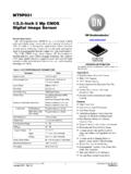
7 High andlow transitions; selectable per inputRecommended Operating ConditionsLevelMinimumMaximum Input high voltage (VIH) VInput low voltage (VIL)0 VOutput high current (IOH) P0.< > -24 mAOutput high current (IOH) PFI < >/P1/P2 -16 mAOutput low current (IOL) P0.< > 24 mAOutput low current (IOL) PFI < >/P1/P2 16 mAElectrical CharacteristicsLevelMinimumMaximum Positive-going threshold (VT+) VNegative-going threshold (VT-) V 3 The digital subsystem does not have its own dedicated internal timing engine. Therefore, a sampleclock must be provided from another subsystem on the Device or an external | | NI 6221 Device SpecificationsLevelMinimumMaximum Delta VT hystersis (VT+ - VT-) V IIL input low current (Vin = 0 V) -10 AIIH input high current (Vin = 5 V) 250 ADigital I/O CharacteristicsFigure 4. DIO Port 0: Ioh versus Voh 50 45 40 35 30 25 20 15 10 5023456 Voh (V)Ioh (mA)55 C; Vdd = V25 C; Vdd = V0 C; Vdd = VFigure 5.
8 DIO PFI/Port 1/Port 2: Ioh versus Voh 50 45 40 35 30 25 20 15 10 5023456 Voh (V)Ioh (mA)55 C; Vdd = V25 C; Vdd = V0 C; Vdd = VNI 6221 Device Specifications | National Instruments | 9 Figure 6. DIO Port 0: Iol versus (V)Iol (mA)55 C; Vdd = V25 C; Vdd = V0 C; Vdd = VFigure 7. DIO PFI/Port 1/Port 2: Iol versus (V)Iol (mA)55 C; Vdd = V25 C; Vdd = V0 C; Vdd = VGeneral-Purpose Counters/TimersNumber of counter/timers2 Resolution32 bitsCounter measurementsEdge counting, pulse, semi-period, period,two-edge separationPosition measurementsX1, X2, X4 quadrature encoding withChannel Z reloading; two-pulse encodingOutput applicationsPulse, pulse train with dynamic updates,frequency division, equivalent time sampling10 | | NI 6221 Device SpecificationsInternal base clocks80 MHz, 20 MHz, MHzExternal base clock frequency0 MHz to 20 MHzBase clock accuracy50 ppmInputsGate, Source, HW_Arm, Aux, A, B, Z,Up_DownRouting options for inputsAny PFI, RTSI, PXI_TRIG, PXI_STAR,analog trigger, many internal signalsFIFO2 samplesData transfersPCI/PXID edicated scatter-gather DMA controller foreach counter/timer.
9 Interrupts, programmed I/OUSBUSB Signal Stream, programmed I/OFrequency GeneratorNumber of channels1 Base clocks10 MHz, 100 kHzDivisors1 to 16 Base clock accuracy50 ppmOutput can be available on any output PFI or RTSI Loop (PLL)Note PCI/PXI devices of PLLs1 Reference signalPXI_STAR, PXI_CLK10, RTSI < >Output of PLL80 MHz Timebase; other signals derived from80 MHz Timebase including 20 MHz and100 kHz TimebasesExternal Digital TriggersSourceAny PFI, RTSI, PXI_TRIG, PXI_STARP olaritySoftware-selectable for most signalsNI 6221 Device Specifications | National Instruments | 11 Analog input functionStart Trigger, Reference Trigger,Pause Trigger, Sample Clock, Convert Clock,Sample Clock TimebaseAnalog output functionStart Trigger, Pause Trigger, Sample Clock,Sample Clock TimebaseCounter/timer functionGate, Source, HW_Arm, Aux, A, B, Z,Up_DownDigital waveform generation (DO)functionSample ClockDigital waveform acquisition (DI)functionSample ClockDevice-to- Device Trigger BusPCIRTSI < >4 PXIPXI_TRIG < >, PXI_STARUSB sourceNoneOutput selections10 MHz Clock, frequency generator output,many internal signalsDebounce filter settings125 ns, s, ms, disable.
10 High andlow transitions; selectable per inputBus V or 5 V signal environmentUSBUSB Hi-Speed or full-speed5, 6 DMA channels (PCI/PXI)6, can be used for analog input, analog output,digital input, digital output, counter/timer 0,counter/timer 1 USB Signal Stream4, can be used for analog input, analog output,counter/timer 0, counter/timer 1 The PXI Device supports one of the following features: May be installed in PXI Express hybrid slots Or, may be used to control SCXI in PXI/SCXI combo chassis4In other sections of this document, RTSI refers to RTSI < > for the PCI devices orPXI_TRIG < > for PXI you are using an USB M Series Device in full-speed mode, Device performance will be lower andyou will not be able to achieve maximum sample/update on a full-speed bus may result in lower | | NI 6221 Device SpecificationsTable 3.