Transcription of Noise Reduction and Isolation - mccdaq.com
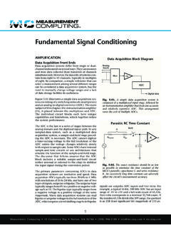
1 Noise Reduction and Isolation CONTROLLING Noise Control Panel Grounding Controlling Noise in measurement systems is vital because it can become a serious problem Utility Circuit breaker Control even in the best instruments and data acquisi- distribution box panel transformer tion hardware. Most laboratories and industrial Hot phase A. environments contain abundant electrical- Noise sources, including AC power lines, heavy Hot phase B. machinery, radio and TV stations, and a variety of electronic equipment. Radio stations generate Neutral high-frequency Noise , while computers and Ground other electronic equipment generate Noise in all frequency ranges.
2 Building a completely Noise - Earth Earth Enclosure free environment just for running tests and ground ground ground measurements is seldom a practical solution. Fortunately, simple devices and techniques such Fig. Utility power transformers are typically as using proper grounding methods, shielded grounded to earth ground near the transformer, and and twisted wires, signal averaging methods, again at the input to the electrical junction box or filters, and differential input voltage amplifiers first switching panel. The switching panel, in turn, can control the Noise in most measurements. may be connected to a rod driven into the earth to ensure that it too is at true ground potential.
3 Some techniques prevent Figurenoise entering the system, while others remove extraneous Noise from the signal. panel in the wired path to the eventual load. (See Figure ) The ground is a point within the THE GROUNDING CONFLICT panel connected to a nearby earth ground rod. A non-technical dictionary defines the term Typically, a large or significant structure (building ground as a place in contact with the earth, a frame) or metallic system (plumbing) is also common return in an electrical circuit, and an connected to the same point. This minimizes arbitrary point of zero voltage potential. voltage differences that may develop between a Grounding, or connecting some part of an elec- water pipe and an appliance with a three-wire trical circuit to ground ensures safety for personnel grounded cord, for example.
4 An electrical fault and it usually improves circuit operation. such as a non-grounded conductor contacting a Unfortunately, a safe environment and a robust metal object is designed to open a fuse or trip a ground system often do not happen simultane- breaker rather than leave an electrically energized ously. It takes planning based on systematically appliance at a higher potential than a nearby understanding how electricity behaves in various water pipe or a sink faucet. If the ground connec- types of circuits. For example, high redundancy tion in the panel disconnects for any reason, the is one key feature that makes most of the elec- redundant ground near the transformer will trical distribution systems around the world safe provide the path for fault currents to open fuses and operate properly.
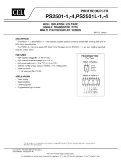
5 Or trip breakers. Preventing electrical shocks and electrical fires is the highest priority for ground Grounding for Safety circuits, but the redundancies built into many Isolated secondaries of step-down power distribu- electrical grounding systems occasionally limit tion transformers are generally grounded near certain kinds of connections for input to data the transformer and within the first switching acquisition systems. 1. Measurement Computing 10 Commerce Way Norton, MA 02766 (508) 946-5100 Common Grounds Interfering Ground loop VCC VS VSS VDD. Sensor RL. + 30 mA. Digital Analog +. circuits circuits 150 mV. ADC +. +. Power ES.
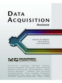
6 Supply Digital Analog Vout Vin = A . ground ground Vout = Preferred common return Default ground 150 mV. + . 30 mA RL. 500 ft. Earth Enclosure ground ground Fig. The 150 mV dropped across RL in the bottom ground return line arises from the 30 mA of current flowing Fig. Significant current fed to multiple circuits should in W of lead wire resistance. The voltage adds to the have individual return paths to a common ground or negative sensor's signal to yield at the input to the terminal. This reduces the risk of voltage drops developing over signal-conditioning amplifier and produces a error. long ground runs or lead wires that could become input (error).
7 Signals to other circuits. Figure few milliseconds and is usually not a safety hazard. But the problem can be much more serious if lightning strikes 2 a safety ground structure and thousands of amperes flow Grounding for Robust Instrumentation through the ground system. Potential differences across Several internal, common busses in a data control instru- even a fraction of an ohm can easily exceed 1,000 VAC. ment are arranged to regulate current flows and terminate and damage equipment and endanger lives. all paths at one common point. This approach ensures that the current flowing in any path will not force a Symptoms of Ground Loops voltage drop in a return path for another circuit and Sometimes, a measurement error is mistakenly attrib- appear as an (erroneous) input signal.
8 (See Figure ) uted to a ground loop problem, especially where a Usually, this one common point connects through low ground is not strictly involved. The phenomenon impedances to the safety ground connection on the relates to two types of situations; shared current flow instrument's AC power cord. This connection prevents in a circuit path, which produces unintended volt- the internal system from floating at an AC potential ages, and inadvertent circuits that interfere with the between earth ground and the input AC supply potential. proper operation of intended circuits. GROUND LOOPS How Ground Loops are Created Measuring instruments that contain an earth ground as A ground loop problem can be illustrated by the described above usually generate a ground loop.
9 A ground following example. An integrated sensor with internal loop can become a serious problem even when the ground signal conditioning contains three wires; a positive voltage on the measured point equals the ground voltage power supply lead, a signal output lead, and a negative entering the instrument through the line cord. A voltage lead that serves as both the power return and signal that develops between the two grounds can be either an common. (See Figure ) The sensor's internal AC or a DC voltage of any value and frequency, and as the circuitry draws about 30 mA and the output signal voltage and frequency increase, the effects of the ground ranges from 0 to 5 VDC.
10 Loop become more troublesome. The sensor is stimulated and a digital voltmeter reads the Dangerous and Destructive Ground Loops correct output of VDC on the test bench. But when A transient current can generate a substantial voltage on the three leads are extended by 500 feet with 20 AWG. grounded conductors. During an electrical fault when an wire ( W/1,000 ft. at 20 C), the common lead wire energized conductor contacts a safety ground, for example, carrying the 30 mA of power supply current drops about a fraction of the supply voltage can end up on the safety 150 mV. This lead resistance voltage drop adds to the ground before the fuse or circuit breaker supplying the sensors output voltage and delivers VDC to the fault opens and removes the voltage.