Transcription of NONLINEAR PATH CONTROL FOR A DIFFERENTIAL …
1 RECENT, Vol. 11, no. 1(28), March, 2010 41 NONLINEAR PATH CONTROL FOR A DIFFERENTIAL drive mobile robot Plamen PETROV, Lubomir DIMITROV Technical University of Sofia, Bulgaria Abstract. A NONLINEAR feedback path controller for a DIFFERENTIAL drive mobile robot is presented in this paper. First, a kinematic model in error coordinates expressed in a moving reference frame partially linked to the robot is developed. The CONTROL law is designed using backstepping method yielding exponential stability of the closed-loop system. Stability analysis is performed via Lyapunov stability theory. Simulation results are presented to illustrate the effectiveness of the proposed controller. Keywords: DIFFERENTIAL drive mobile robot , path following, NONLINEAR CONTROL , integrator backstepping 1.
2 Introduction During the last two decades, the wheeled mobile robots have been increasingly presented in industrial and service robotics. In order to perform a task with a mobile robot , one needs to solve many problems from task planning to motion CONTROL design. At CONTROL level, important results have been established concerning specific CONTROL tasks as point stabilization (the parking problem), trajectory tracking and path following. Beyond the relevance in applications, stabilizing a mobile robot at given posture leads to specific CONTROL problems. It is known [1] that feedback point stabilization of nonholonomic systems like wheeled mobile robots can not be achieved via smooth time-invariant CONTROL law due to limitations imposed by Brockett s necessary condition [2] for feedback stabilization of such a system.
3 Furthermore, the linearization of a nonholonomic system about any equilibrium point is uncontrollable and consequently, linear analysis and design techniques cannot be applied [3]. The alternative approaches can be classified as smooth NONLINEAR time-varying feedback stabilization [4] and discontinuous NONLINEAR time-invariant stabilization [5]. For trajectory tracking and path following tasks, standard linear [6] and NONLINEAR approaches are effective (feedback linearization [7], Lyapunov-based techniques [8, 9, 10]). The most common way to build a mobile robot is to use two-wheel drive with DIFFERENTIAL steering and a free balancing wheel (castor). Controlling the two motors independently, such robots have good maneuvering and work well indoors on flat surfaces.
4 Many commercial platforms based on this locomotion scheme exist, such as the mobile robot Pioneer 3-DX [11] from ROBOSOFT. In this paper, we present a NONLINEAR feedback path following controller for a DIFFERENTIAL drive mobile robot and in particular, with application to mobile robot Pioneer 3-DX [11]. The design procedure is based on integrator backstepping method. Stability analysis is performed via Lyapunov techniques. The paper is organized as follows: In Section 2, the kinematic model of the robot is presented. In Section 3, the path following problem in error coordinates expressed in a moving reference frame partially linked to the vehicle is stated. In Section 4, the design of the proposed controller and stability analysis is given.
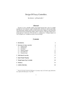
5 Simulation results are presented in Section 5. Section 6 contains some conclusions and future work. 2. Kinematic model The mobile robot Pioneer 3-DX considered in this paper is shown in Figure 1. It is an advanced research robot that can has an on-board PC, a range of sensors like a camera and laser rage finder, and communicates via WiFi (Wireless Ethernet). Figure 1. The mobile robot Pioneer 3-DX Defining the Larson-Miler Parameter for a New Alloy Steel 42 RECENT, Vol. 11, nr. 1(28), Martie, 2010 The kinematic scheme of the robot consists of platform with two driving wheels mounted on the same axis with independent actuators and one free wheel (castor). The mobile robot is steered by changing the relative angular velocities of the driving wheels.
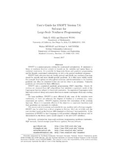
6 It is assumed that the wheels are non-deformable and roll without lateral sliding. A plan view of the robot moving on a horizontal plane is shown in Figure 2. Figure 2. A plan view of the robot Point P located at the center of the driving wheel axle is used as a reference point of the robot . If the inertia of the wheels with respect to their proper axes is ignored, the configuration of the system can be described by three generalized coordinates =PPyxq, (1) where (xP, yP) are the coordinates of point P and is the orientation of the robot with respect to an inertial coordinate frame FXY (Figure 2). The system is characterized by the following nonholonomic constraint on the generalized velocities q& 0= qA&, (2) where A is a 1 3 matrix as follows []0cossin =A.
7 (3) The mobile robot has two degrees of freedom in the plane. The constraint equation (2) can be converted in an affine driftless CONTROL system =Cq&, (4) where the columns of the 3 1 matrix C(q) =100sin0cosC (5) form a basis of the null space of matrix A(q). The CONTROL inputs is a 2 1 vector of independent quasi-velocities of the form = = PPPxyxv&&1000sincos, (6) where vPx is the velocity of point P and = & is the angular velocity of the robot . The angular velocities of the driving wheels []T21, = &&& are related to the quasi-velocities trough the following expressions = &D, (7) where =drdrrrD2222 (8) is 2 2 invertible matrix; r is the wheel radius and d is the lateral semi-base of the robot .
8 3. Problem formulation The path following geometry used in this paper is presented in Figure 2. Consider a DIFFERENTIAL - drive robot moving on a flat surface. It is assumed that the path C is a smooth planar curve. A moving reference coordinate frame RxRyR is defined such that the xR axis is tangent to the path and oriented in the direction of motion to follow, and the yR axis passes through the reference point P of the robot . It is supposed that the distance between points P and R is smaller than the reference curvature radius at point R and in that way, ensuring that the reference path is uniquely defined [4]. Using the frames Pxy and RxRyR, the position and orientation of the mobile robot with respect to the moving reference frame, , the error coordinates e = [ex, ey, e ]T can be obtained by geometrical projection transformation as follows = rrrPrrrryxyyxxeeeP1000cossin0sincos, (9) where [xP, yP, ]T and [xr, yr, r]T are the position and orientation of the frames Pxy and RxRyR with respect to an inertial frame FXY.
9 Defining the Larson-Miler Parameter for a New Alloy Steel RECENT, Vol. 11, no. 1(28), March, 2010 43 Differentiating (9) and taking into account the nonholonomic constraints, after some work [12], the error dynamics of the robot is obtained in the form ,000000001000cossin0sincos0 ++ + = eeeveeeeveeeyxrrPxRRxyx&&& (10) where &and r r &. It is assumed that the robot linear velocity vPx(t) is bounded ()(tvctevPxPxMax =) and does not converge to zero. Since the Ryr axis of frame RxRyR (Figure 2) passes through the reference point P of the robot , from the first equation of (10), it follows that 0)( xxetе&. (11) Using (11), from the first equation of (10), the reference angular velocity r = vRx/ r of the frame RxRyR can be expressed as a function of the velocity of the mobile robot as follows yrPxrrecevc = 1cos, (12) where cr = 1/ r is the curvature of the reference path at point R.
10 Finally, using (11), from the second and third equations of (10), an error dynamics which is appropriate for path following applications can be derived in the form ,,sin)( = =eeetvеPxy&& (13) where re = . (14) with r obtained from (12). In this case, using the parameterization (ex, ey, e ) and given a path C, under the assumptions that 0)(>= ctevtvPxPx and |cr ey| < 1, the path following problem consists of finding a feedback CONTROL = (vPx, ey, e , cr) for the system (13) such that .0)(lim,0)(lim00== tetetyt (15) 4. NONLINEAR CONTROL design In this Section, a NONLINEAR controller based on a backstepping design method [13] is presented. The CONTROL objective is to regulate the lateral and orientation errors (ey, e ) to zero.