Transcription of Op Amp Precision Design: DC Errors - Microchip Technology
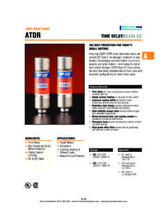
1 AN1177. Op Amp Precision design : DC Errors Author: Kumen Blake DC SPECIFICATIONS. Microchip Technology Inc. There are a small number of DC specifications that describe Errors at the input of an op amp. This section INTRODUCTION organizes these specifications into those related to the input offset and the others related to input bias Engineers that use op amps in their circuits; especially currents. those new to analog or op amp circuit design . Also intended for engineers that want to understand op amp Ideal Op Amp DC specifications. Figure 1 shows the ideal, DC model for op amps (the Description external circuitry is not shown).
2 All error sources are ignored and the open-loop gain (AOL) is infinite. The This application note covers the essential background output voltage is related to the input voltages as shown information and design theory needed to design a in Equation 1. Precision DC circuit using op amps. Topics include: Op Amp DC Specifications VN. Circuit Analysis VOUT. Circuit Optimization AOL. VI. Advanced Topics References FIGURE 1: Ideal, DC Op Amp Model. This application note is limited to voltage feedback (traditional) op amps. Those interested in current feed- EQUATION 1: back op amps will benefit from the information here; the DC specifications and op amp DC model have many V OUT = A OL ( V N V I ).
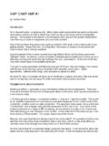
3 Similarities. For those that are interested, a simple circuit for When negative feedback is applied, the ideal op amp's measuring input offset voltage has been included in infinite gain forces VN and VI to be exactly equal; this is Appendix A: Input Offset Measurement Circuit . the virtual short that some authors talk about. [ 1, 2]. When positive feedback is applied ( , when used as a comparator), VOUT swings as far negative or positive as it can (to the rails), depending on the sign of the dif- ference (VN VI). Op Amp Model with DC Errors Figure 2 shows a physically based, DC model for op amps.
4 VPLUS and VMINUS are the external input volt- ages, while VN and VI are the internal input voltages. VOST represents the total input offset voltage error. The non-inverting bias current (IBN) and inverting bias cur- rent (IBI) represent the physical currents seen at each of the two input pins. AOL is the finite DC open-loop gain. 2008 Microchip Technology Inc. DS01177A-page 1. AN1177. It is important to understand the units for these VDD specifications. An engineer not used to op amp data sheets may be confused by the units shown. The following list should clear up the confusion.
5 VOST. VN VOS units are: mV or V. VPLUS AOL units do not usually report the relationship VOUT. VMINUS AOL shown above: VI. - V/V for 1/AOL = VOST/ VOUT. - dB for 20log(AOL). IBN IBI CMRR units are similar to the AOL units: - V/V for 1/CMRR = VOST/ VCM. - dB for 20log(CMRR). VSS. PSRR units are similar to the AOL units: FIGURE 2: Physically Biased, DC Op - V/V for 1/PSRR = VOST/ (VDD VSS). Amp Model. - dB for 20log(PSRR). Input Offset Related Specifications VOS/ TA units are: V/ C or nV/ C. A positive VOST creates a positive shift in the output Note: Notice that the gains AOL, CMRR and voltage (VOUT).
6 The DC voltages are: PSRR, when reported in V/V, are actually their reciprocals. This form of the gains is EQUATION 2: best for statistical analyses; the values tend to have a Gaussian distribution. V N = V PLUS + V OST. V I = V MINUS Sometimes PSRR is split in two pieces: PSRR+ that is related to changes in VDD ( VDD) and PSRR that is V OUT = A OL ( V N V I ). related to changes in VSS ( VSS). = A OL ( ( V PLUS V MINUS ) + V OST ). These quantities are lumped together in the following equation, where the changes in bias voltages are from The total input offset voltage (VOST) collects the those specified for VOS (all units are converted to either following specifications into one, easy to use V or V/V): parameter: Input Offset Voltage (VOS): EQUATION 3: - Specified offset V OUT V CM V.
7 DD V SS V OS. - Describes VOST at a specific bias point V OST = V OS + -------------------- + ----------------- + ----------------- + --------------- + T A ---------------- A. OL. CMRR PSRR PSRR TA. DC Open-Loop Gain (AOL): - AOL = VOUT/ VOST Notice that all of the specifications will give a positive Common Mode Rejection Ratio (CMRR): change in VOST when the corresponding changes are positive. - CMRR = VCM/ VOST. - VCM is the common mode input voltage (average of VPLUS and VMINUS). Input Current Related Specifications Power Supply Rejection Ratio (PSRR): The input bias currents (IBN and IBI) create voltage - PSRR = (VDD VSS)/ VOST drops across external resistances, which cause VOUT.
8 Input Offset Drift with Temperature ( VOS/ TA): to shift. By convention, the currents going into the pins VPLUS and VMINUS are positive. - Describes how VOST changes with TA;. actually VOST/ TA Traditionally, these physically based currents have - TA is the ambient temperature been mathematically transformed into the equivalent pair of currents IB (input bias current) and IOS (input off- set current). These are the average of IBN and IBI, and their difference, respectively: EQUATION 4: ( I BN + I BI ). I B = -------------------------- 2. I OS = I BN I BI. DS01177A-page 2 2008 Microchip Technology Inc.
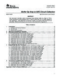
9 AN1177. This model makes sense for traditional op amps that CIRCUIT ANALYSIS. have IBN and IBI nearly equal. This means that, in this case, IB is much larger than IOS. This happens because Using a few simple techniques, it is easy to analyze the these currents are caused by similar physically DC error performance of op amp circuits. Several phenomena ( , matched transistor pair with similar common circuits illustrate these techniques. input bias currents). Figure 2 shows how these specified currents are modeled in a circuit. Resistance Seen by the Non-inverting Input VDD. Figure 4 is a simple circuit with a source and several impedances attached to the non-inverting input.
10 The VOST process of calculating the equivalent resistance seen VN. VPLUS by the non-inverting input will be described using this VOUT circuit as the starting point. VMINUS AOL. VI. R1 L1. U1. IB + IOS/2 IB IOS/2 VOUT. V1 C1 R2. VSS. FIGURE 3: Equivalent DC Model for FIGURE 4: Simple Circuit. Traditional Op Amps. The first step is to replace all external components with Some newer op amp architectures have IOS near to the their DC equivalent for a Thevenin analysis: same magnitude as IB. This happens because the Voltage sources become 0V (short circuit). physical causes of IBN and IBI are not physically related Current sources become 0A (open circuit).