Transcription of Operating and Installation Instructions - ari …
1 Rev. 0040501000 3116 general information on Operating Notes on possible dangers .. Significance of symbols .. Explanatory notes on safety information .. Storage and transport .. Description .. Field of application .. Method of Diagram .. ARI-PREMIO 2,2 - 5 kN .. ARI-PREMIO 12 - 15 kN .. Parts list .. Technical data .. Dimensions .. Installation .. general Installation data .. Manual operation .. ARI-PREMIO 2,2 - 5 kN .. ARI-PREMIO 12 - 15 kN .. 2-16 Operating and Installation Instructions Thrust actuator ARI-PREMIO ContentsPage 2-20040501000 3116 Operating and Installation instructionsThrust actuator ARI-PREMIO Installation Instructions for mounting to Mounting for valve-lift up to 30 mm (yoke version) .. Mounting for valve lift over 30 mm to 80 mm (column version) .. Electrical connection .. Wiring diagram ARI-PREMIO 2,2 - 15 kN 1Ph~.. ARI-PREMIO 2,2 - 15 kN Standard .. ARI-PREMIO 2,2 - 15 kN 24V AC/DC / 24V DC pole-changing.
2 Wiring diagram ARI-PREMIO 2,2 - 15 kN 3Ph~.. ARI-PREMIO 12 - 15 kN 3 Ph~ with reversing contactor / external reversing contactor .. Connection .. Options and settings .. Torque and travel switches .. Connection boards PA (only 2,2 - 5 kN) or NA (2,2 - 15 kN) .. Travel switch .. Installation of additional travel Installation of trip slide and setting of the travel switch (S3) .. Setting the additional travel switches (S4/S5 and S24/S25).. Installing the Setting the FError-proof potentiometer for single-channel, error-proof position feedback .. Setting the T V-approved potentiometer on conductive plastic Heating .. Installation of heating .. Electronic position indicator Electronic position controller ES11 .. Electronic position indicator (RI21) and position controller (ES11) together in the actuator .. Integrated temperature controller dTRON 316 .. Installation of the dTRON Integrated reversing contactor .. Installing the reversing contactor.
3 Electrical connection with ES11 or dTRON 316 .. Diagram AC/DC-Version with BLDC motor .. Optional board support with pole changing for 24V DC .. Electronic position indicator Useful range of the linear motion potentiometer .. Installing the RI32 electronic position indicator in the ARI-PREMIO .. Electronic position indicator (RI32) and position controller (ES11) together in the actuator .. Technical data - Position indicator Potentiometer Installation .. Wiring Connection conditions .. Setting zero point and slope Putting the actuator into operation .. Care and maintenance .. Troubleshooting .. Troubleshooting table .. Dismantlement of thrust Warranty / Guarantee .. Original Declaration of Incorporation and Conformity .. 2-520040501000 3116 Page 2-3 Operating and Installation instructionsThrust actuator ARI-PREMIO general information on Operating instructionsThese Operating Instructions provide information on mounting and maintaining the thrust actuators.
4 Please contact the supplier or the manufacturer in case of problems which cannot be solved by reference to the Operating are binding on the transport, storage, Installation , start-up, operation, maintenance and notes and warnings must be observed and adhered Handling and all work must be carried out by expert personnel or all activities must be supervised and is the owner s responsibility to define areas of responsibility and competence and to monitor the In addition, current regional safety requirements must be applied and observed when taking the fittings out of service as well as when maintaining and repairing manufacturer reserves the right to introduce technical modifications at any Operating Instructions comply with the requirements of EU Notes on possible dangers Significance of symbols ATTENTION !..Warning of general !..Warning of dangerous to injury! Don t touch the turning handwheel when the motor is to injury! Don t put your hand into the up or downwards moving when not observing the Operating and Installation Instructions !
5 Before installing, Operating , maintenance or dismantling read and observe the though voltage! Before dismantling the hood, switch of the electrical source and secure against turning on 2-40040501000 3116 Operating and Installation instructionsThrust actuator ARI-PREMIO Explanatory notes on safety informationIn these Operating and Installation Instructions dangers, risks and items of safety information are highlighted to attract special marked with the above symbol and ATTENTION ! describe practices, a failure to comply with which can result in serious injury or danger of death for users or third parties or in material damage to the system or the environment. It is vital to comply with these practices and to monitor other information not specifically emphasised such as transport, Installation , Operating and maintenance Instructions as well as technical data (in the Operating Instructions , product documentation and on the device itself) must also be complied with to the fullest extent in order to avoid faults which in turn can cause serious injury to persons or damage to Storage and transport - At -20 to +70 C dry, free from Do not unpack thrust drive or setting equipment assembly prior to Installation .
6 - Protect against external force (impact, vibration etc.).- Do not soil or damage type identification plate and wiring diagram on the ! - Valve mountings such as drives, handwheels, hoods must not be used to take external forces, they are not designed for use as climbing aids, or as connecting points for lifting may lead to death, injury or damage to property due to persons falling or parts being Suitable materials handling and lifting equipment should be Technical data for 3116 Page 2-5 Operating and Installation instructionsThrust actuator ARI-PREMIO Field of applicationARI-PREMIO linear thrust actuators are employed to actuate control or shut-off valves requiring a nominal linear stroke distance of up to 80 mm and thrust from kN to 15 kN. The thrust actuators are set to the thrust forces specified in the technical data. If supplied with the valve, the lift of the thrust actuator will be set to the stroke distance of the of the proper actuator version in alignment with the corresponding fitting as well as use of the thrust actuator in accordance with the specified technical data is the responsibility of the systems data sheet for areas of application, application limits and use of the thrust actuator beyond the specified technical data or improper use of the actuator is deemed to be not for the intended ambient conditions have to be conform to the actual electromagnetic compatibility directives.
7 Additional the compatibility to this directives has to be maintained in case of expansion or other changing of the ambient Method of functioningThe thrust actuator, fitted with a yoke or columns, is mounted to the of force is effected via a coupling safeguarded against torsion safeguarding feature also serves as a lift lift settings can be read off on a lift dial attached to the yoke or between the 2-ear clamps mounted to the electrical components are accommodated separately from the gearbox underneath a sealed hood, thus being protected against Operating and environmental removal of the hood, easy access is provided to the switchgear and indicating rotary motion of the motor is transmitted to the spindle nut by means of spur drive spindle, which is safeguarded against torsion, screws its way into the spindle nut and thus performs a pull or push motion depending on the sense of the final positions of the valve, the spindle nut is pressed against a set of springs so as to produce closing motor is switched-off by means of two load-dependent switches and one stroke-dependent switch.
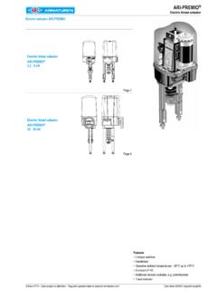
8 For the function of the stroke-dependent travel switch (S3), an optionally available trip slide is necessary. The load-dependent switches will also switch-off the motor if foreign bodies have lodged themselves between the valve seat and load-dependent switches serve to protect the valve and thrust actuator against 2-60040501000 3116 Operating and Installation instructionsThrust actuator ARI-PREMIO ARI-PREMIO 2,2 - 5 kNFig. 1 Yoke VersionColumn VersionSynchronous motor115V AC - 230V ACBLDC motor24V AC/DC0040501000 3116 Page 2-7 Operating and Installation instructionsThrust actuator ARI-PREMIO ARI-PREMIO 12 - 15 kNFig. 2 Synchronous motor115V AC - 230V ACBLDC motor24V AC/DCPage 2-80040501000 3116 Operating and Installation instructionsThrust actuator ARI-PREMIO Parts list cover screw DIN ISO 4766 - gland 2 x M16x1,5 / 1 x M20x1, screw DIN motor, plug 1 x M16x1, Head cap screw DIN EN ISO 4762-M4 - screw DIN EN ISO 10642 - washer DIN EN ISO 7089 -5, switch (valve up) Torque spring handle of diagram sticker, washer DIN , 3-pole (standard) head screwDIN EN ISO 4017 - cap screwDIN EN ISO 4762 - head screwDIN EN conductor bolt DIN cap screw DIN EN ISO 4762 - DIN EN ISO washer DIN DIN 3771 4 x nut DIN EN ISO 4032 - , DIN 3771 - nut DIN EN ISO 7042 - clamp (stroke indicator)
9 Nut Seal lock safety bolt safety cap screw M4x180040501000 3116 Page 2-9 Operating and Installation instructionsThrust actuator ARI-PREMIO Technical data TypeARI-PREMIO Thrust forcekN2,25,012,015,0 Control speed ,380,381,00,380,790,38 Stroke distance max. mm5080 Duty classification acc. to EN 60034-1S3 80% ED / c/hS3 50% ED / max. 1200 c/hSupply voltage230V - 50Hz / 60Hz 1)230V - 50 HzMotor typeSynchronous motorPower consumptionW213375698569 For power consumption of other voltages and frequencies refer to type plate or on switch2 pcs., permanently wired, switching capacity 10A, 250V~ 2 pcs., permanently wiredswitching capacity 16A, 250V~Travel switch 2)1 pcs., permanently wired, switching capacity 10A, 250V~ 1 pcs., permanently wiredswitching capacity 16A, 250V~Enclosure EN 60529IP 65 Max. storage temperature-40 C .. +85 CMax. permissible ambient temperature-20 C .. +70 CFor operation outside or at freezing temperature a heating is (rotating during operation)Yes (engageable)Operation3-step Max.
10 Cable cross section3-step input: 2,5 mm2 Mounting positionAny. Exception: motor must not be suspended downwardsGear lubricantKl ber Isoflex Topas NB152 Molyduval Valenzia H2 Weight kg5,46,06,510,51) Control speed and power consumption are 20% higher at frequency of 60 Hz 2) Option trip slide necessaryPage 2-100040501000 3116 Operating and Installation instructionsThrust actuator ARI-PREMIO Additional voltages / frequenciesSynchronous motorTypeARI-PREMIO Thrust forcekN2,25,012,015,0 Control speedmm/s0,380,381,00,380,79 0,38 Supply voltageV - Hz115 V - 50/60 Hz 1) 3~400 V - 50/60 Hz 1)115V - 50/60Hz 1) 3~400V - 50/60Hz 1)115V - 50Hz / 115V - 60Hz 1)230V - 60Hz 1) 3~400 V - 50 Hz / 3~400 V - 60 Hz 1)Duty classification acc. to EN 60034-1115V - 230 V: S3 80% ED / max. 1200 c/h 400 V: S3 50% ED / max. 1200 c/hS3 50% ED / max. 1200 c/hPower consumptionrefer to type plate or on requestBLDC-Motor (Brushless DC motor)TypeARI-PREMIO Thrust forcekN2,2 kN 5,0 kN 12,0 kN15,0 kN Control speedmm/s0,380,381,00,380,790,38 Supply voltageV - Hz24 V - AC / DC (further information refer to point AC/DC-Version)Duty classification acc.