Transcription of Phase Locked Loops (PLL) and Frequency Synthesis
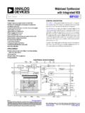
1 Berkeley Phase Locked Loops (PLL) and Frequency Synthesis Prof. Ali M. Niknejad Berkeley Copyright c 2014 by Ali M. Niknejad Niknejad PLLs and Frequency Synthesis Phase Locked Loop Block Diagram Loop Filter Ref PD VCO. Div N. Phase Locked Loops (PLL) are ubiquitous circuits used in countless communication and engineering applications. Components include a VCO, a Frequency divider, a Phase detector (PD), and a loop filter. Niknejad PLLs and Frequency Synthesis Phase Locked Loops A PLL is a truly mixed-signal circuit, involving the co-design of RF, digital, and analog building blocks. A non-linear negative feedback loop that locks the Phase of a VCO to a reference signal. Applications include generating a clean, tunable, and stable reference (LO) Frequency , a process referred to as Frequency Synthesis Other applications: Frequency modulation and demodulation (a natural FM modulator/demodulator).
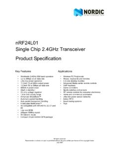
2 Clock recovery for high speed communication, and the generation of Phase synchronous clock signals in microprocessors. Electronic PLLs are common, but optical and mechanical also used. Niknejad PLLs and Frequency Synthesis Frequency synthesizer In a Frequency synthesizer , the VCO is usually realized using an LC tank (best Phase noise), or alternatively a ring oscillator (higher Phase noise, smaller area). The reference is derived from a precision XTAL oscillator. The divider brings down the high Frequency of the VCO signal to the range of the reference Frequency . The PD compares the Phase and produces an error signal, which is smoothed out by the loop filter and applied to the VCO. When the system locks, the output Phase of the VCO is Locked to the XTAL. That means that the Frequency is also Locked . The output Frequency fout is therefore an integer multiple of the reference fref fref = fout /N fout = N fref Niknejad PLLs and Frequency Synthesis Programmable Divider By making the divider N programmable, we can tune the VCO Frequency in either integer steps of the reference (integer-N architecture) or in fractional amounts (fractional-N.)
3 Architecture). f = (N + p)fref Nfref = pfref In a fractional divider, p < 1 and is realized by dithering the divider between N and N + 1 using a sigma-delta modulator. In practice, the programmable divider is made of up asynchronous high-speed dividers followed by programmable CMOS dividers (counters). The high speed dividers are sometimes in CML, which runs faster than CMOS, and has superior noise immunity and generation due to the differential nature. Injection Locked or TSPC dividers are also useful for very low power high Frequency operation. Niknejad PLLs and Frequency Synthesis Capture Range and Linear Model A PLL is described by several parameters, such as the locking range, or the range of frequencies for which it will stay Locked . The capture range is the Frequency range for which it will lock from an initially unlocked state. The capture range is smaller than the locking range.
4 These parameters are hard to derive analytically and require simulation. But the dynamics of the loop, such as settling time, the noise transfer characteristics ( Phase noise), can be derived from a linear model. Therefore it is useful to derive a linear model by assuming the system is close to lock, or in lock. The most convenient variable is Phase , and not Frequency , in the linear model. Since Phase and Frequency are related, it's easy to go back and forth. Niknejad PLLs and Frequency Synthesis KVCO. out (rad/sec). K V CO FVCO = KVCO Vctrl FVCO. KVCO =. Vctrl Vctrl The VCO tuning curve is generally non-linear and given by a plot of output Frequency versus control voltage. But when the PLL is in lock, the control voltage Vctrl varies only around a small region around the lock point. We can therefore model the VCO linearly. Since we are interested in the Phase , and observing that Frequency is the time derivative of Phase , we can derive 1 KVCO.
5 VCO = FVCO = Vctrl s s The VCO is therefore an implicit integrator in the loop. This is an important fact to consider when designing a PLL. Niknejad PLLs and Frequency Synthesis Divider Linear Model From a voltage input-output characteristic, the divider is a non-linear block that simply acts like a counter. For N input edges, only one output edge occurs. But in terms of Phase , it's a linear block FVCO. FDiv =. N. Z t Z t FVCO. Div = FDiv ( )d = ( )d . N. Z t 1 1. = FVCO ( )d = VCO. N N. The linear gain is just the division ratio. Niknejad PLLs and Frequency Synthesis Multiplier Phase Detector The most classic Phase detector (PD) is a multiplier. Consider the product of two sinusoids offset by some Phase . The product is simply given by AB. e(t) = AB cos( t) cos( t + ) = (cos( ) cos(2 t + )). 2. After a low-pass filter (LPF), the high Frequency term at twice the Frequency is filtered out AB.
6 < e(t) >= cos( ). 2. The slope of the Phase detector around zero is given by de(t) AB. KPD = = sin . d 2. Niknejad PLLs and Frequency Synthesis Multiplier Phase Detector (cont). In Locked condition, the Phase deviations are small and we can make the simple linear approximation AB. KPD . 2. Note that this system will lock the VCO onto the quadrature of the reference signal. The negative sign is not much concern, because it can be absorbed into other gain blocks which have positive or negative gains, depending on how they are designed. We must ensure that the overall loop has negative Phase shift to form negative feedback. Some designers reserve the option to swap the inputs of the PD just to be sure they can change things in case they make an error! Niknejad PLLs and Frequency Synthesis XOR Phase Detector Ref Div XOR. XOR. The differential XOR gate acts very much like a multiplier.
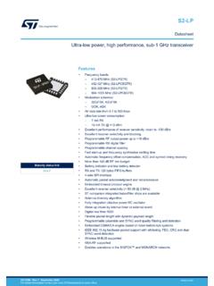
7 The best way to derive the transfer function is just to draw some ideal digital signals at the inputs and outputs and to find the average level of the output signal. Note that the output is at twice the input Frequency (just like the multiplier) and a D C shift, which depends on the relative balance of the waveforms. The average value of the output is a linear function of the Phase difference, which is exactly what we want. Niknejad PLLs and Frequency Synthesis XOR Phase Detector < e ( t) >. Ref Div +1. XOR. 0 err . XOR. 2 2. 1. A sketch of the transfer curve shows that the system will also lock in quadrature (if perfectly balanced). The slope of the line determines the PD gain, KPD = 1. Note that in quadrature the duty cycle of the positive and negative outputs is balanced, which produces a zero average output. Also note that the PD function is also periodic, much like the multiplier.
8 In fact, the schematic of a XOR (CML) and a multiplier are very similar except for the signal levels. Niknejad PLLs and Frequency Synthesis Phase Detector Linear Model As we have seen, the Phase detector is actually a non-linear block that only extracts the Phase on an average sense. We use the PD average behavior in the linear model. On average, the PD produces an error signal by taking the difference between the reference Phase and the divided VCO. Phase . The PD gain is related to the slope of the transfer function e(t) = KPD ( ref (t) Div ). Niknejad PLLs and Frequency Synthesis Loop Filter The loop filter is an linear filter that smooths out the error signal and is a critical part of the system under the control of the designer. Passive RC and active filters are both used to realize the loop filter. Ideally the voltage on the control node of a VCO should settle to a DC value to avoid reference spurs.
9 In other words, if we apply a periodic waveform on the control line, we get FM. side-bands which are undesirable. Since the PD block is non-linear and non-ideal, even in lock it can produce a waveform that needs to be filtered to minimize reference spurs. Niknejad PLLs and Frequency Synthesis Complete Linear Model + err VC KVCO. REF KPD H(s) LO. s div 1. N. The loop gain is given by KPD H(s)KVCO. A(s) =. Ns Niknejad PLLs and Frequency Synthesis Closed-Loop Gain The closed loop gain is given by PD KVCO H(s)K. A s G (s) = =. 1 + Af 1 + KPD H(s)K. Ns VCO. This is simplified to KPD H(s) KVCO. N. G (s)/N =. s + KPD H(s) KVCO. N. Niknejad PLLs and Frequency Synthesis Noise Transfer Function If we consider the Phase noise coming out of the VCO, its transfer function to the output is different and given by (also the transfer function for the error signal). 1 s E (s) = =.
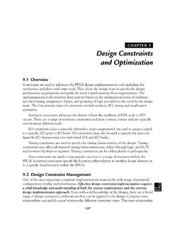
10 1 + A(s) s + KPD H(s) KVCO. N. The VCO noise is therefore attenuated by the loop gain, which is very nice since the reference is usually much more spectrally pure than the VCO (it is typically constructed using a high-Q quartz resonator) whereas the VCO uses a low Q. on-chip tank (inductor + varactor). Note that when the loop gain drops (outside of the bandwidth of the PLL), the noise of the PLL is essentially governed by the free-running noise of the VCO. Niknejad PLLs and Frequency Synthesis Case 1: No Loop Filter 40 5. Magnitude (dB). 20 0. 0 -5. -20. -10. Magnitude (dB). -40. 1 10 100 -15. Normalized Frequency -20. 0. -25. -45. Phase (deg). -90 -30. -135 -35. G(s)/N E(s). -180 -40. 1 10 100 1 10 100. Normalized Frequency Normalized Frequency If we omit a loop filter, H(s) = 1, the loop gain is given by 1. A(s) = Ns KPD KVCO and the closed loop gain and error function are low-pass and high-pass respectively KPD KVCO.