Transcription of myDAQ How-to Guide
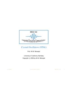
1 Leland Au 1 myDAQ How-to Guide Leland Au, UC Berkeley Intro USB: 1. Type B USB port 2. Blue LED Indicator Audio: 3. Audio In 4. Audio Out Power Supply: 5. +15V: +15V Power Supply 6. -15V: -15V Power Supply 7. AGND: Power Supply Ground Analog Input: 8. AO0: Analog Output 0 9. AO1: Analog Output 1 10. AGND: Analog Input/Output Ground Analog Output: 11. AI0+: Analog Input 0, Positive Terminal 12. AI0-: Analog Input 0, Negative Terminal 13. AI1+: Analog Input 1, Positive Terminal 14.
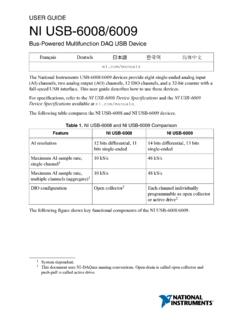
2 AI1-: Analog Input 1, Negative Terminal Digital Input/Output: 15. DIO: Digital Input/Output Pins 0-7 16. DGND: Digital Input/Output Ground 17. 5V: 5V Digital Power Supply Digital Multimeter: 18. HI: Positive Terminal for V, ,Diode (60V Max) 19. COM: Common Ground 20. HI: Positive Terminal for Current (1A Max) Installation notesi: 1. Make sure to install LABVIEW, NI ELVISmx, and Multisim (the installation times are specified in the installer as well) 2. Information releasing and NI update installer: up to you 3.
3 Full name and company: up to you 4. Serial numbers are on the Certificate of Ownership (see Materials ) 5. Several dialogs requiring user interaction will appear during installation. 6. Installation time: about 45 minutes 7. Restart your computer after installation. Kit Materials (from the box): 1 myDAQ 1 male-to-male audio cable 2 banana cables with probes 1 USB A/B cable 1 screw-terminal connector 1 CD 1 Certificate of Ownership (this contains software and driver license serial numbers) 1 screwdriver 1 Quick Start Guide Basic Usage (bolded numbers refer to the myDAQ diagram) To enable the myDAQ : 1.
4 Plug in one end of the USB cable to the computer, and the other end to the top of the myDAQ (1) 2. A blue LED indicator on top of the myDAQ will turn on (2) Using the screw terminals (5-17): Attach the screw-terminal connector Insert/remove wires when the appropriate screw is loose. Turn the appropriate screw counterclockwise (with the screwdriver) to loosen. Turn the appropriate screw clockwise to tighten. 15V Power Supply (non-adjustable): 1. Insert a wire into the +15V power supply (5) and/or -15V power supply (7) (see Using the terminals ) 2.
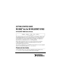
5 Insert a wire into AGND (5) 3. Connect wires to the appropriate places in your circuit NI ELVISmx (virtual instruments)ii Launch: Start -> All Programs -> National Instruments -> NI ELVISmx for NI ELVIS & NI myDAQ -> NI ELVISmx Instrument Launcher 1. DMM: Digital Multimeter 2. Scope: Oscilloscope 3. FGEN: Function Generator 4. Bode: Bode Analyzer 5. DSA: Dynamic Signal Analyzer 6. ARB: Arbitrary Waveform Generator 7. DigIn: Digital Reader 8. DigOut: Digital Writer Leland Au 2 Digital Multimeter Launch: NI ELVISmx Instrument launcher -> DMM 1.
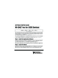
6 Measurement settings a. DC Voltage (60V Max) b. AC Voltage (60V Max) c. DC Current (1A Max) d. AC Current (1A Max) e. Resistance f. Diode g. Continuity 2. Mode: Auto (recommended) or Specify Range (and set the limit under Range ) 3. Device: Should include (NI myDAQ ) 4. Banana Jack Connections: The arrows indicate where to connect the banana cables to on the myDAQ (18-20) 5. Run: Starts the multimeter 6. Stop: Stops the multimeter Oscilloscope Launch: NI ELVISmx Instrument Launcher -> Scope 1.
7 Source: Input channel from the myDAQ (either AI0(11) or AI1(13)). Make sure the negative terminal of the corresponding channel goes to ground (12 or 14, respectively) 2. Enable: Make sure this is checked to view the channel 3. Device: Should include (NI myDAQ ) 4. Autoscale: Press to fit data on the viewer 5. Run: Starts the oscilloscope 6. Stop: Stops the oscilloscope 7. Cursors On: Enable to read the current data point 8. Display Measurements: Enable for RMS voltage, frequency, and peak-to-peak voltage Function Generator Launch: NI ELVISmx Instrument launcher -> FGEN 1.
8 Waveform: Sine, triangle, or square waveforms 2. Frequency: Waveform frequency (Hz) 3. Amplitude: Waveform peak-to-peak voltage (Vpp) 4. DC Offset: Constant offset to waveform 5. Device: Should include (NI myDAQ ) 6. Signal Route: Output channel to myDAQ (AO0(8) or AO1(9)) 7. Run: Starts the function generator 8. Stop: Stops the function generator i For Macs, refer to Basically, you need Windows on the Mac. ii The grayed-out instruments in the launcher and DMM require an NI ELVIS system.
9