Transcription of Connector Accessory for E/M/S Series Devices
1 INSTALLATION GUIDEBNC-2120 Connector Accessory for E/M/S Series DevicesThis installation guide describes how to install, configure, and use your BNC-2120 Accessory with 68-pin or 100-pin E/M/S Series multifunction data acquisition (DAQ) Devices . This document also contains Accessory BNC-2120 has the following features: Eight BNC connectors for analog input (AI) connection Onboard temperature reference Thermocouple Connector Resistor measurement screw terminals Two BNC connectors for analog output (AO) connection Screw terminals for digital I/O (DIO) connection with state indicators Screw terminals for timing I/O (TIO) connection Two user-defined BNC connectors A function generator with the following outputs: Frequency-adjustable, TTL-compatible square wave Frequency- and amplitude-adjustable sine wave or triangle wave Quadrature encoder A 68-pin I/O Connector that connects to multifunction DAQ Devices Can be used on a desktop or mounted on a DIN railContentsConventions.
2 2 What You Need to Get started .. 2 Installing the BNC-2120 .. 2 Connecting Analog Input Signals .. 5 Connecting Differential Analog Input Signals .. 5 Measuring Floating Signals .. 5 Measuring Ground-Referenced 6 Measuring Temperature .. 6 Measuring Resistance .. 7 Connecting Analog Output Signals .. 7 Using the Function 8 Connecting Timing I/O Signals .. 8 Using the Quadrature 10 Connecting User-Defined Signals .. 10 Connecting Digital I/O 11 BNC-2120 Installation following conventions are used in this document:< >Angle brackets that contain numbers separated by an ellipsis represent a range of values associated with a bit or signal name for example, AO < >. The symbol leads you through nested menu items and dialog box options to a final action.
3 The sequence File Page Setup Options directs you to pull down the File menu, select the Page Setup item, and select Options from the last dialog icon denotes a note, which alerts you to important icon denotes a caution, which advises you of precautions to take to avoid injury, data loss, or a system crash. When this symbol is marked on a product, refer to the Read Me First: Safety and Radio-Frequency Interference document for information about precautions to text denotes items that you must select or click in the software, such as menu items and dialog box options. Bold text also denotes parameter text denotes variables, emphasis, a cross-reference, or an introduction to a key concept. Italic text also denotes text that is a placeholder for a word or value that you must in this font denotes text or characters that you should enter from the keyboard, sections of code, programming examples, and syntax examples.
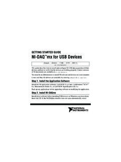
4 This font is also used for the proper names of disk drives, paths, directories, programs, subprograms, subroutines, device names, functions, operations, variables, filenames, and You Need to Get StartedTo set up and use your BNC-2120 Accessory , you need the following: BNC-2120 Accessory /accessories1 BNC-2120 Installation guide One of the following DAQ Devices : 68-pin E/M/S Series device (with one or two I/O connectors )2 100-pin E Series device Cable(s) for DAQ device(s), as listed in Table 1 The E Series User Manual, the M Series User Manual, or the S Series User Manual BNC cables 28 16 AWG wire Wire strippers Flathead screwdriverInstalling the BNC-2120 Figure 1 shows the front panel of the You can use two BNC-2120 accessories with both connectors of NI6224/6229/6254/6259/6284/6289 M Series You cannot use the BNC-2120 with Connector 1 of NI 6225/6255 Devices .
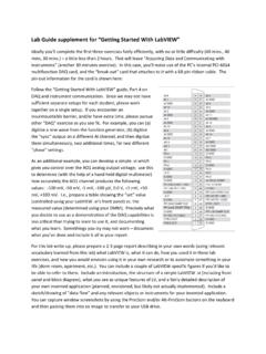
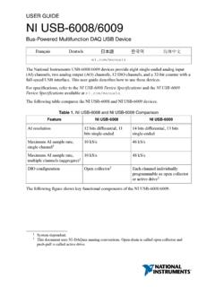
5 National Instruments Corporation3 BNC-2120 Installation GuideFigure 1. BNC-2120 Front Panel1 RES/BNC Switch (AI 3)2 Resistor Measurement Screw Terminals3 Thermocouple Input Connector4 Temperature Reference5 BNC/Temp. Ref. Switch (AI 0)6 BNC/Thermocouple Switch (AI 1)7 Analog Input BNC Connectors8FS/GS Switches9 Analog Output BNC Connector10 Frequency Range Selection Switch11 Sine/Triangle BNC Connector12 TTL Square Wave BNC Connector13 Sine/Triangle Waveform Switch14 Frequency Adjust Knob15 Amplitude Adjust Knob16 Digital I/O Screw Terminals17 Digital I/O LEDs18 User-Defined Screw Terminals19 User-Defined BNC Connectors20 Timing I/O Screw Terminals21 Quadrature Encoder Screw Terminals22 Quadrature Encoder Knob23 Timing I/O BNC Connector24 Power Indicator LEDELRTTSNINAMUNOIASTN_+FloatingSource (FS)_+Ground (GS)
6 AOANALOG OUTPUTSANALOG INPUTSDIGITAL I/OFUNCTION GENERATORF requency SelectionAmplitude AdjustSine / TriangleTTL Square WaveFrequency AdjustGSFSGSFSGSFSGSFSGSFSGSFSGSFSGSFSAI 0AI 1 USER 1 USER GNDAI 2 BNCRES+AI GNDAI kHzLOHILOHI1-100 kHz13-1000 kHzThermocoupleBNCRESAI 3 BNCAI 3AI 4AI 5AI 6AI 7AO 0AO 1 USER-DEFINEDSIGNALS**For BNC connections, wire any Timing I/O or Digital I/O screw terminals I/OPFI 0 / Pulses / RevQuadratureEncoderPFI 1 / 2 / 3 / 4 / 5 / 6 / 7 / 8 / 9 / 12 / 13 / 14 / +5 VPULSESUP / DND !101617157984621214131115192023222421318 BNC-2120 Installation connect the BNC-2120 to your DAQ device, complete the following steps. Consult your computer or PXI/PXI Express chassis user manual for specific instructions and you have not already installed your DAQ device, refer to the daq getting started guide for not connect the BNC-2120 to any device other than National Instruments E/M/S Series multifunction DAQ Devices .
7 Doing so can damage the BNC-2120, the DAQ device, or the host computer. National Instruments is not liable for damage resulting from these the BNC-2120 near the host computer or PXI/PXI Express chassis or use the optional DIN Rail Mounting kit for UMI-FLEX-6 and BNC boxes (part number 777972-01), which you can order from National Instruments at not connect input voltages greater than Vpk/60 VDC to the BNC-2120. The BNC-2120 is not designed for any input voltages greater than Vpk/60 VDC, even if a user-installed voltage divider reduces the voltage to within the input range of the DAQ device. Input voltages greater than Vpk/60 VDC can damage the BNC-2120, all Devices connected to it, and the host computer. Overvoltage can also cause an electric shock hazard for the operator.
8 National Instruments is not liable for damage or injury resulting from such the BNC-2120 to the DAQ device using the appropriate cable for your DAQ device, aslisted in Table power indicator LED, shown in Figure 1, lights. If it does not light, check the cable Measurement & Automation Explorer (MAX), confirm that your DAQ device is recognized, and configure your device settings. Refer to the daq getting started guide for more signals to the BNC connectors and screw terminal block as described in the following NI-DAQmx, National Instruments has revised its terminal names so they are easier to understand and more consistent among NI hardware and software products. The revised terminal names used in this document are usually similar to the names they replace.
9 For a complete list of Traditional NI-DAQ (Legacy) terminal names and their NI-DAQmx equivalents, refer to the Terminal Name Equivalents table in the NI-DAQmx 1. BNC-2120 Cabling OptionsNumber of PinsDAQ DeviceRecommended Cable(s)68-pinDAQCard E Series , NI PCI/PCIe/PXI/PXIe M Series *NI 6143 S SeriesSHC68-68-EPM or RC68-68 PCI/PXI E Series , USB Mass Termination M Series *, NI 611x/612x/613x S Series SH68-68-EPM or R6868 100-pinPCI/PXI E SeriesSH1006868* You cannot connect the BNC-2120 to Connector 1 of NI 6225/6255 Devices . Do not use the R6868 cable with NI 6115/6120 S Series Devices ; use only the SH68-68-EPM cable. National Instruments Corporation5 BNC-2120 Installation specific device functionality, such as the ability to send and receive data with MAX test panels.
10 Refer to the daq getting started guide for detailed information about running test panels in you have finished using the BNC-2120, power off any external signals connected to the BNC-2120 before you power off your Analog Input SignalsYou can use the analog input BNCs on the BNC-2120 in the following ways: Measure differential AI signals, as described in the Connecting Differential Analog Input Signals section Measure temperature, as described in the Measuring Temperature section Measure resistance, as described in the Measuring Resistance sectionConnecting Differential Analog Input SignalsUse the BNC-2120 BNC connectors on the front panel to connect AI < > signals to your DAQ device. The BNC-2120 is only intended for differential analog input signals.