Transcription of PIC16F87/88 Data Sheet - Microchip Technology
1 PIC16F87/88 . 18/20/28-Pin Enhanced Flash MCUs with nanoWatt Technology Low-Power Features: Pin Diagram Power-Managed modes: 18-Pin PDIP, SOIC. - Primary Run: RC oscillator, 76 A, 1 MHz, 2V. - RC_RUN: 7 A, kHz, 2V RA2/AN2/CVREF/. VREF- 1 18 RA1/AN1. - SEC_RUN: 9 A, 32 kHz, 2V. RA3/AN3/VREF+/. - Sleep: A, 2V C1 OUT 2 17 RA0/AN0. Timer1 Oscillator: A, 32 kHz, 2V RA4/AN4/T0 CKI/ 3 16 RA7/OSC1/CLKI. C2 OUT. Watchdog Timer: A, 2V RA5/MCLR/VPP. PIC16F88. 4 15 RA6/OSC2/CLKO. Two-Speed Oscillator Start-up VSS 5 14 VDD. RB7/AN6/PGD/. Oscillators: RB0/INT/CCP1 (1). 6 13 T1 OSI. Three Crystal modes: RB1/SDI/SDA 7 12 RB6/AN5/PGC/. T1 OSO/T1 CKI. - LP, XT, HS: up to 20 MHz RB2/SDO/RX/DT 8 11 RB5/SS/TX/CK. Two External RC modes (1). RB3/PGM/CCP1 9 10 RB4/SCK/SCL.
2 One External Clock mode: - ECIO: up to 20 MHz Note 1: The CCP1 pin is determined by the CCPMX bit in Internal oscillator block: Configuration Word 1 register. - 8 user selectable frequencies: 31 kHz, 125 kHz, 250 kHz, 500 kHz, 1 MHz, 2 MHz, 4 MHz, 8 MHz Special Microcontroller Features: 100,000 erase/write cycles Enhanced Flash Peripheral Features: program memory typical Capture, Compare, PWM (CCP) module: 1,000,000 typical erase/write cycles EEPROM. - Capture is 16-bit, max. resolution is ns data memory typical - Compare is 16-bit, max. resolution is 200 ns EEPROM data Retention: > 40 years - PWM max. resolution is 10-bit In-Circuit Serial Programming (ICSP ). 10-bit, 7-channel Analog-to-Digital Converter via two pins Synchronous Serial Port (SSP) with SPI Processor read/write access to program memory (Master/Slave) and I2C (Slave) Low-Voltage Programming Addressable Universal Synchronous In-Circuit Debugging via two pins Asynchronous Receiver Transmitter Extended Watchdog Timer (WDT): (AUSART/SCI) with 9-bit address detection: - Programmable period from 1 ms to 268s - RS-232 operation using internal oscillator (no external crystal required) Wide operating voltage range: to Dual Analog Comparator module.
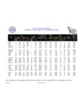
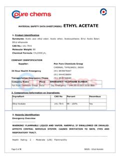
3 - Programmable on-chip voltage reference - Programmable input multiplexing from device inputs and internal voltage reference - Comparator outputs are externally accessible Program Memory data Memory I/O 10-bit CCP Timers Device Flash # Single-Word SRAM EEPROM AUSART Comparators SSP. Pins A/D (ch) (PWM) 8/16-bit (bytes) Instructions (bytes) (bytes). PIC16F87 7168 4096 368 256 16 N/A 1 Y 2 Y 2/1. PIC16F88 7168 4096 368 256 16 1 1 Y 2 Y 2/1. 2002-2013 Microchip Technology Inc. DS30487D-page 1. PIC16F87/88 . Pin Diagrams 18-Pin PDIP, SOIC. RA2/AN2/CVREF 1 18 RA1/AN1. RA3/AN3/C1 OUT 2 17 RA0/AN0. RA4/T0 CKI/C2 OUT 3 16 RA7/OSC1/CLKI. PIC16F87. RA5/MCLR/VPP 4 15 RA6/OSC2/CLKO. VSS 5 14 VDD. RB0/INT/CCP1(1) 6 13 RB7/PGD/T1 OSI. RB1/SDI/SDA 7 12 RB6/PGC/T1 OSO/T1 CKI.
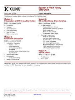
4 RB2/SDO/RX/DT 8 11 RB5/SS/TX/CK. RB3/PGM/CCP1(1) 9 10 RB4/SCK/SCL. 20-Pin SSOP. RA2/AN2/CVREF 1 20 RA1/AN1. RA3/AN3/C1 OUT 2 19 RA0/AN0. RA4/T0 CKI/C2 OUT 3 PIC16F87 18 RA7/OSC1/CLKI. RA5/MCLR/VPP 4 17 RA6/OSC2/CLKO. VSS 5 16 VDD. VSS 6 15 VDD. RB0/INT/CCP1(1) 7 14 RB7/PGD/T1 OSI. RB1/SDI/SDA 8 13 RB6/PGC/T1 OSO/T1 CKI. RB2/SDO/RX/DT 9 12 RB5/SS/TX/CK. RB3/PGM/CCP1(1) 10 11 RB4/SCK/SCL. 18-Pin PDIP, SOIC. RA2/AN2/CVREF/VREF- 1 18 RA1/AN1. RA3/AN3/VREF+/C1 OUT 2 17 RA0/AN0. RA4/AN4/T0 CKI/C2 OUT 3 16 RA7/OSC1/CLKI. PIC16F88. RA5/MCLR/VPP 4 15 RA6/OSC2/CLKO. VSS 5 14 VDD. RB0/INT/CCP1(1) 6 13 RB7/AN6/PGD/T1 OSI. RB1/SDI/SDA 7 12 RB6/AN5/PGC/T1 OSO/T1 CKI. RB2/SDO/RX/DT 8 11 RB5/SS/TX/CK. RB3/PGM/CCP1(1) 9 10 RB4/SCK/SCL. 20-Pin SSOP. RA2/AN2/CVREF/VREF- 1 20 RA1/AN1.
5 RA3/AN3/VREF+/C1 OUT 2 19 RA0/AN0. RA4/AN4/T0 CKI/C2 OUT 3 18 RA7/OSC1/CLKI. PIC16F88. RA5/MCLR1/VPP 4 17 RA6/OSC2/CLKO. VSS 5 16 VDD. VSS 6 15 VDD. RB0/INT/CCP1(1) 7 14 RB7/AN6/PGD/T1 OSI. RB1/SDI/SDA 8 13 RB6/AN5/PGC/T1 OSO/T1 CKI. RB2/SDO/RX/DT 9 12 RB5/SS/TX/CK. RB3/PGM/CCP1(1) 10 11 RB4/SCK/SCL. Note 1: The CCP1 pin is determined by the CCPMX bit in Configuration Word 1 register. DS30487D-page 2 2002-2013 Microchip Technology Inc. PIC16F87/88 . Pin Diagrams (Cont'd). RA4/T0 CKI/C2 OUT. RA3/AN3/C1 OUT. RA2/AN2/CVREF. 28-Pin QFN(1). RA1/AN1. RA0/AN0. NC. NC. 28. 27. 26. 25. 24. 23. 22. RA5/MCLR/VPP 1 21 RA7/OSC1/CLKI. NC 2 20 RA6/OSC2/CLKO. VSS 3 19 VDD. NC 4 PIC16F87 18 NC. VSS 5 17 VDD. NC 6 16 RB7/PGD/T1 OSI. RB0/INT/CCP1(2) 7 15 RB6/PGC/T1 OSO/T1 CKI.
6 10. 11. 12. 13. 14. 8. 9. NC. NC. RB1/SDI/SDA. RB2/SDO/RX/DT. RB3/PGM/CCP1(2). RB5/SS/TX/CK. RB4/SCK/SCL. RA4/AN4/T0 CKI/C2 OUT. RA3/AN3/VREF+/C1 OUT. 28-Pin QFN(1). RA2/AN2/CVREF/VREF- RA1/AN1. RA0/AN0. NC. NC. 28. 27. 26. 25. 24. 23. 22. RA5/MCLR/VPP 1 21 RA7/OSC1/CLKI. NC 2 20 RA6/OSC2/CLKO. VSS 3 19 VDD. NC 4 PIC16F88 18 NC. VSS 5 17 VDD. NC 6 16 RB7/AN6/PGD/T1 OSI. RB0/INT/CCP1(2) 7 15 RB6/AN5/PGC/T1 OSO/T1 CKI. 10. 11. 12. 13. 14. 8. 9. NC. NC. RB1/SDI/SDA. RB2/SDO/RX/DT. RB3/PGM/CCP1(2). RB5/SS/TX/CK. RB4/SCK/SCL. Note 1: For the QFN package, it is recommended that the bottom pad be connected to VSS. 2: The CCP1 pin is determined by the CCPMX bit in Configuration Word 1 register. 2002-2013 Microchip Technology Inc. DS30487D-page 3.
7 PIC16F87/88 . Table of Contents Device Overview .. 5. Memory Organization .. 11. data EEPROM and Flash Program 27. Oscillator Configurations .. 35. I/O Ports .. 51. Timer0 Module .. 67. Timer1 Module .. 71. Timer2 Module .. 79. Capture/Compare/PWM (CCP) Module .. 81. Synchronous Serial Port (SSP) Module .. 87. Addressable Universal Synchronous Asynchronous Receiver Transmitter (AUSART) .. 97. Analog-to-Digital Converter (A/D) Module .. 113. Comparator 121. Comparator Voltage Reference Module .. 127. Special Features of the CPU .. 129. Instruction Set Summary .. 149. Development 157. Electrical Characteristics .. 161. DC and AC Characteristics Graphs and Tables .. 191. Packaging 205. Appendix A: Revision 215. Appendix B: Device 215. INDEX.
8 217. The Microchip Web Site .. 225. Customer Change Notification Service .. 225. Customer Support .. 225. Reader Response .. 226. PIC16F87/88 Product Identification System .. 227. TO OUR VALUED CUSTOMERS. It is our intention to provide our valued customers with the best documentation possible to ensure successful use of your Microchip products. To this end, we will continue to improve our publications to better suit your needs. Our publications will be refined and enhanced as new volumes and updates are introduced. If you have any questions or comments regarding this publication, please contact the Marketing Communications Department via E-mail at or fax the Reader Response Form in the back of this data Sheet to (480) 792-4150. We welcome your feedback.
9 Most Current data Sheet To obtain the most up-to-date version of this data Sheet , please register at our Worldwide Web site at: You can determine the version of a data Sheet by examining its literature number found on the bottom outside corner of any page. The last character of the literature number is the version number, ( , DS30000A is version A of document DS30000). Errata An errata Sheet , describing minor operational differences from the data Sheet and recommended workarounds, may exist for current devices. As device/documentation issues become known to us, we will publish an errata Sheet . The errata will specify the revision of silicon and revision of document to which it applies. To determine if an errata Sheet exists for a particular device, please check with one of the following: Microchip 's Worldwide Web site; Your local Microchip sales office (see last page).
10 When contacting a sales office, please specify which device, revision of silicon and data Sheet (include literature number) you are using. Customer Notification System Register on our web site at to receive the most current information on all of our products. DS30487D-page 4 2002-2013 Microchip Technology Inc. PIC16F87/88 . DEVICE OVERVIEW TABLE 1-1: AVAILABLE MEMORY IN. PIC16F87/88 DEVICES. This document contains device specific information for the operation of the PIC16F87/88 devices. Additional Program data data Device information may be found in the PIC Mid-Range MCU Flash Memory EEPROM. Family Reference Manual (DS33023) which may be PIC16F87/88 4K x 14 368 x 8 256 x 8. downloaded from the Microchip web site. This Reference Manual should be considered a comple- There are 16 I/O pins that are user configurable on a mentary document to this data Sheet and is highly pin-to-pin basis.