Transcription of POER - IXYS Corporation
1 ISOPLUS i4-PACTM half - bridge MOSFET ModulesIXYS introduces new half - bridge MOSFET modules that are available in IXYS proprietary ISOPLUS i4-PACTM packaging. These modules provide unsurpassed thermal performance and temperature cycling capabilities making them ideal for applications utilizing power semiconductor devices that require heat sink grounding methods. These devices are also suitable for designers who seek isolated half - bridge configurations integrated into one single package avoiding the use of multiple discrete devices thus promoting critical board layout space savings. The ISOPLUS i4-PACTM is a UL recognized isolated package incorporating a direct copper bond (DCB) ceramic isolator which provides 2500 Vrms isolation between die and heat sink.
2 The i4-PACTM yields as high as a 45% decrease in junction to heat sink thermal resistance R(th)js, providing superior thermal performance over packages utilizing external mounted isolation materials. These modules exhibit improved switching behavior due to low inductive current paths as dies are located within one package. An additional feature includes a reduction in EMI emissions due to the low coupling capacitance between die and heat sink. These half - bridge modules take full advantage of proven technology platforms commonly implemented in both the IXYS Trench and Polar discrete MOSFET product families. These new modules are currently available in two configurations.
3 One configuration (Part number prefix denoted as FMP) combines carefully selected P-Channel and N-Channel mosfets configured in a phase-leg or half - bridge topology with a common drain arrangement. An added benefit from this configuration is the elimination of gate drive circuitry normally required in driving an N-Channel MOSFET on the high-side of a phase leg, resulting in a component count reduction, thus improving drive circuit simplicity, space savings, and over-all component cost. The other configuration (Part number prefix denoted as FMM) is comprised of two N-Channel mosfets situated on both the low and high side of the phase leg.
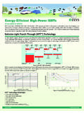
4 The Dual N-Channel FMM modules are capable of accommodating drain to source breakdown voltages of 75V, 150V, 200V, 250V, 500V and 600V with drain current values from 12 amperes to 120 amperes. The P&N FMP modules are available to support applications requiring drain to source breakdown voltages of -200V, -150V, and -100V with drain current ratings from -54 amperes to -17 amperes. A broad range of applications stands to benefit from these new half - bridge MOSFET modules. These applications include DC/AC motor drives, uninterruptible power supplies, switch mode power supplies, solar/wind power inverters, synchronous rectifiers, industrial battery chargers, Class AB audio amplifiers and multi-phase DC to DC 2010nEW PrODuCT BrIEFOVErVIEWIXyS InTrODuCES nEW ISOlaTED PhaSE lEg mODulESFEaTurESSilicon chip on Direct-Copper Bond (DCB)
5 SubstrateUL recognized package Isolated mounting surface 2500V electrical isolation Avalanche rated Low drain-to-tab capacitance Low drain to ground capacitance Low package inductance High power density aPPlICaTIOnSDC and AC motor drives Class AB audio amplifiers Multi-phase DC to DC converter Industrial battery chargers Switching-mode & resonant- mode power supplies DC choppers Uninterruptible power supplies Synchronous rectifiers Solar and wind power inverters BEnEFITS Low gate drive requirement Fast switching Easy to mount Space savings POWERE fficiency Through i4-PaCTm half - bridge mOSFET Summary TableApplication CircuitsISOPluSTm Packages with Internal Alumina DCB Isolation*EmIFilterBridgeRectifierBoostP FCC ontrol and Gate Drive CircuitryQ1D1C1L1 BuckFull-BridgeXenonIgniterConverterInve rterLampControl UnitandGate DriveVinVoutC1T1D1D2C3L1 LoadGate Drive ICDzRzRh1Rh2 DhChD1Rl1 InRl2 Bond wiresLeadsCopperCopperSolderCeramicDCBCh ipMouldFmm1 Fmm2 FmP1 Fmm1 Fmm2 Full- bridge DC to DC ConverterFMP Single Gate Drive CircuitThe figure above exhibits a FMP half - bridge MOSFET Module (Combines a P-Channel and N-Channel MOSFET in a half - bridge , common drain configuration)
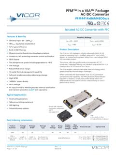
6 Driven by only one gate drive IC. The principle benefit from this configuration is the elimination of gate drive circuitry normally required in driving an N-channel MOSFET on the high side of a phase leg, resulting in a component count reduction, thus improving drive circuit simplicity, space savings, and over-all figure above depicts a general full- bridge power converter. IXYS FMM and FMP MOSFET Modules are ideally suited for use in many DC to DC converter topologies. A pair of FMM MOSFET Modules are utilized to drive the primary side of transformer T1. D1 and D2 diodes provide for rectification and to serve as free-wheeling diodes on the secondary side of T1 before entering a low pass HID Lamp Ballast DiagramThe figure on the left depicts a basic high intensity discharge (HID) lamp ballast diagram, suitable for general outdoor applications.
7 A pair of FMM MOSFET Modules (FMM1 and FMM2) are employed in a full- bridge configuration at the output stage of this general HID ballast diagram. This lamp ballast performs five basic operations. AC mains enters an EMI filter to block ballast-generated noise. The AC input voltage is then processed in to a DC value via a bridge rectifier. This DC value enters a power-factor-correction (PFC) stage to ensure a sinusoidal input current. A buck converter stage controls HID lamp ballast current before entering the output stage which is comprised of a full- bridge circuit used for driving the HID lamp. Package AdvantagesProvides 2500V, UL recognized isolation with superior thermal performance (E153432).
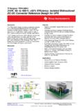
8 Improves termperature and power cycling capability. Cost effective clip mounting. * Patent No. 6,404,065; 6,404,065; 6,534,343; 6,583,505; 6,710,463; 6,731,002; 7,005,734* For information regarding IXYS ISoPLUS packages, visit figure on the right illustrates an ISOPLUSTM 247 cross section. ISOPLUSTM package provides improved creepage distance to simplify compliance with regulatory high-voltage spacing requirements. The copper-bonded, isolated ceramic substrate enhances overall device reliability by greatly improving thermal and power cycling, and the isolated backside simplifies mounting while yielding superior thermal impedance.
9 The molding epoxies utilized meet the UL 94V-0 flammability up with multiple Patents and UL recognition, the ISOPLUSTM packaging advantage is available only from number Vdss max (V)ID(cont) Tc=25oC (a)Rds(on) max Tj=25oC (mW)Ciss typ(pf) Qg typ(nC)tf typ(ns)tr typ(ns)RthJC max(oC/W) 2010