Transcription of Power Amplifiers - Learn About Electronics
1 AC THEORY MODULE 1 E. COATES 2007 -2012 Power Amplifiers Introduction to Power Amplifiers Power Amplifiers amplifier circuits form the basis of most electronic systems, many of which need to produce high Power to drive some output device. Audio amplifier output Power may be anything from less than 1 Watt to several hundred Watts. Radio frequency Amplifiers used in transmitters can be required to produce thousands of kilowatts of output Power , and DC Amplifiers used in electronic control systems may also need high Power outputs to drive motors or actuators of many different types. This module describes some commonly encountered classes of Power output circuits and techniques used to improve performance.
2 Amplifiers Module 5 What you ll Learn in Module 5. Section Introduction to Power Amplifiers . Understand the Operation of Power Amplifiers . Section Power Transistors & Heat Sinks. Power Transistor Construction. Power De-rating & High Power Operation. Thermal Resistance of Heat Sinks. Thermal Runaway. Section Class A Power Amplifiers . The limitations due to the efficiency of class A Power Amplifiers . Transformer coupled Class A Power output stages. Section Class B Amplifiers . Class B biasing. Crossover distortion. Class B biasing. Push-pull output. Advantages & disadvantages of class B. Section Push-pull Driver Stages. Driver transformers. Transistor phase splitter stages.
3 Emitter coupled phase splitter. Transformerless push-pull. Section Class AB Amplifiers . Complementary Outputs. Temperature & DC stabilisation. Mid-point & crossover adjustment. NFB & Bootstrapping. Section amplifier Classes C to H. Class C operation. Class D Power amplifier operation. Class E & F Power Amplifiers . Class G & H Power Amplifiers . Power Amplifiers Quiz. Test your knowledge and understanding of Power Amplifiers . Power Amplifiers Amplifiers MODULE 2 E. COATES 2007 - 2017 The voltage Amplifiers described in Amplifiers Modules 1 to 4 can increase the amplitude of a signal many times but may not, on their own, be able to drive an output device such as a loudspeaker or motor.
4 For example a voltage amplifier may have a gain of 100 and be able to amplify a 150mV signal to an amplitude of 15V and it is quite possible that the amplifier can feed that 15V signal into a load of say 10K , but if the load is changed to a value of 10 , the voltage amplifier would not be able to provide the extra current needed to maintain an output voltage of 15V across 10 . Likewise, a current amplifier may have a gain of 100 and be able to amplify a 10 A signal to 1mA at a very low output voltage, but be unable to supply a 1mA signal at say 10V. In either case the voltage or current amplifier does not have sufficient Power (volts V x current I). Voltage and current Amplifiers can make use of small transistors and do not draw large amounts of Power from the Power supply in order to amplify signals by often, very large amounts.
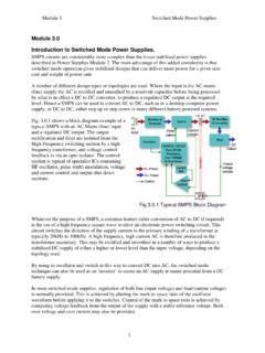
5 However the small transistors they use have very tiny junction areas and so cannot handle the Power needed to drive some output devices without overheating. Power Amplifiers Amplifiers MODULE 3 E. COATES 2007 - 2017 Module Power Transistors & Heat Sinks Power Transistors There is not a clear cut difference between ordinary transistors used in voltage Amplifiers and Power transistors, but generally Power transistors can be categorised as those than can handle more than 1 Ampere of collector (or Drain in the case of FETs) current. Because Power transistors, such as those shown in Fig.
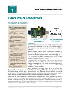
6 Handle larger currents and higher voltages, they have a different construction to small signal devices. They must have low output resistances so that they can deliver large currents to the load, and good junction insulation to withstand high voltages. They must also be able to dissipate heat very quickly so they do not overheat. As most heat is generated at the collector/base junction, the area of this junction is made as large as possible. Power and Temperature The maximum Power rating of a transistor is largely governed by the temperature of the collector/base junction as can be seen from the Power de-rating graph in Fig. If too much Power is dissipated, this junction gets too hot and the transistor will be destroyed, a typical maximum temperature is between 100 C and 150 C, although some devices can withstand higher maximum junction temperatures.
7 The maximum Power output available from a Power transistor is closely linked to temperature, and above 25 C falls in a linear manner to zero Power output as the maximum permissible temperature is reached. What you ll Learn in Module After studying this section, you should be able to: Recognise Power transistor construction. Understand the need to connect the collector and metal case. Understand the relationship between Power and temperature in Power trainsistors. Power De-rating. Understand the need for heat sinks. Methods for choosing heat sinks. Methods for fitting heat sinks. Calculate Thermal Resistance requirements for heat sinks. Power Amplifiers Amplifiers MODULE 4 E.
8 COATES 2007 - 2017 Power De-rating For example, a transistor such as the TIP31 having a quoted maximum Power output PTOT of 40W can only handle 40W of Power IF the case temperature (slightly less than the junction temperature) is kept below 25 C. The performance of a Power transistor is closely dependant on its ability to dissipate the heat generated at the collector base junction. Minimising the problem of heat is approached in two main ways: 1. By operating the transistor in the most efficient way possible, that is by choosing a class of biasing that gives high efficiency and is least wasteful of Power . 2. By ensuring that the heat produced by the transistor can be removed and effectively transferred to the surrounding air as quickly as possible.
9 Method 2 above, highlights the importance of the relationship between a Power transistor and its heat sink, a device attached to the transistor for the purpose of removing heat. The physical construction of Power transistors is therefore designed to maximise the transfer of heat to the heat sink. In addition to the usual collector lead-out wire, the collector of a Power transistor, which has a much larger area than that of a small signal transistor, is normally in direct contact with the metal case of the transistor, or a metal mounting pad, which may then be bolted or clipped directly on to a heat-sink. Typical metal cased and metal body Power transistors are shown in Fig. Because Power Amplifiers generate substantial amounts of heat, which is wasted Power , they are made to be as efficient as possible.
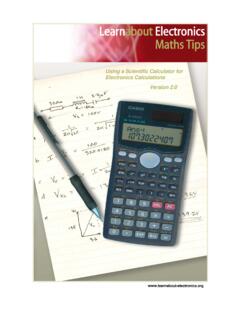
10 With voltage Amplifiers , low distortion is of greater importance than efficiency, but with Power Amplifiers , although distortion cannot be ignored, efficiency is vital. Heat-sinks A heat-sink is designed to remove heat from a transistor and dissipate it into the surrounding air as efficiently as possible. Heat-sinks take many different forms, such as finned aluminium or copper sheets or blocks, often painted or anodised matt black to help dissipate heat more quickly. A selection of heat-sinks is illustrated in Fig. Good physical contact between the transistor and heat-sink is essential, and a heat transmitting grease (heat-sink compound) is smeared on the contact area before clamping the transistor to the heat-sink. Where it is necessary to maintain electrical insulation between transistor and heat-sink a mica layer is used between the heat-sink and transistor.