Transcription of Power Factor Controller BR6000 - …
1 Power Factor Controller BR6000 . Manual Version E. Version E, Apr. 2005. CONTENTS. Section 1 General 3. Section 2 Installation of the Controller / connection diagram 5. Current measurement Programming of phase-correction in special systems Alarm output / fault messages Section 3 Operating modes and programming 7. Automatic operation / display functions Programming Programming lock Section 4 Manual operation / Programming of fixed stages 13. Section 5 Service menu, Test run 14. Section 6 Expert mode 15. Section 7 Initial operation 16. Section 8 Control principle 16.
2 Section 9 Interface 17. Section 10 Maintenance and warranty 17. Section 11 Troubleshooting 18. Section 12 Technical data 19. Annex: Annex 1 Table of control series 20. Description of control-series editor Annex 2 Default settings 21. Annex 3 Controller coupling 22. Annex 4 MODBUS Protocol 23. Operating diagram (Brief programming) 25. -2- Section1 General The Power Factor Controller BR6000 is a modern control device of innovative design with a variety of functions. It features a user interface with a menu-driven display in plain text for maximum ease of operation.
3 Straightforward symbols and alphanumeric displays in the language of the country of use (seven languages) combine maximum ease of handling with convenient presentation of results. Display of various grid parameters, storage of various values and a test run option make it easy to analyse errors and monitor the system. An installed base of very high number of PFC controllers underlines the positive acceptance of this product among customers and its high degree of reliability. Additional features: R Six or 12 switching outputs (depending on the version). R Switching outputs with a relay or transistor output R Twenty pre-programmed control series with a self-optimized intelligent control response R Control-series editor for user-defined control series R Complete menu-guided operation and display R Illuminated graphic display with 2 x 16 characters R Four-quadrant operation R Display of various line parameters (V, I, F, Q, P, ).
4 R Display of voltage and current harmonics R Display of temperature R Monitoring of the individual capacitor Power values R Storage of maximum line-parameter and switching-operation values as well as of the turn-on times of individual capacitor contactors R Manual / automatic operation R Programming of fixed stages and the option of skipping individual outputs R No-voltage turn-off R Fault detection for various statuses and interference-message output R Test run of PFC system with error analysis R Switchboard-integrated housing 144x144x55 mm Type series and accessories BR6000 -R6 6 relays outputs, 1 alarm relay BR6000 -T6 6 transistor outputs, 1 alarm relay, relays BR6000 -R12 12 relay outputs, 1 alarm relay BR6000 -T12 12 transistor outputs, 1 alarm relay, relay Option /F Input for second target cos phi additional user programmable message relay Controller coupling possible Option /S As option /F with additional interface RS232 or RS485, MODBUS oder ASCII.
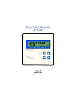
5 Accessories - Meas. voltage adapter for grids without N or voltages above 300V. - Current Measuring Module (for measurement of inherent current of capacitor bank ). - Remote indication -3- The Controller is supplied as standard for an operating voltage of 230 VAC (L-N), a measuring voltage of VAC (L-N) 50/60 Hz and a measuring current of 5A or 1A. (programmable). A voltage converter is required for different operating voltages. Fig. 1 BR6000 front view Operating mode - Automatic - Programming - Manual operation - Service COS j =0, 98 I ND - Expert mode Enter / OK.
6 Confirm and 1 2 3 4 5 6 7 8 9 10 11 12. store values Power Factor Controller BR 6000. Blindleistungsregler Reguladores Automaticos de Energia Reactiva Auto Program Increase Manual Service selected parameter Enter OK. cos j Reduce selected parameter Fig. 2 BR6000 rear view Power Factor Controller BR6000 -R12. BR6000 -R12- meas. voltage: 30 -300V L-N 50/60Hz supply voltage: 230V L-N 50/60Hz : supply- meas. meas. current 1. capacitor- voltage voltage Im (5A/1A) branch Ub Um k l L1 (R). L2 (S). L3 (T). N. PE. T 6,3A. T 2A. T 2A. only BR6000 - 12. L N L N k l RS 232 *.
7 Ub Um Im P1 P2. K1. Power Factor * option Controller BR6000 . a b 1 2 3 4 5 6 7 8 9 10 11 12. alarm- * target COSPHI2 *. relay capacitor capacitor contactors 1-6 contactors 7-12. supply meas. meas. alarm- voltage voltage current relay L N L N k l a b P1 K1 K2 K3 K4 K5 K6. 2. Cos j Message external relays X. RS232 Rs485 Without Interface * P2 K7 K8 K9 K10 K11 K12. GND B A SL. -4- Section 2 Installation and connection of the Controller The BR6000 is designed to be incorporated into the front panel of a PFC-cabinet. It requires a switchboard section of 138 x 138 mm to DIN 43 700.
8 The Controller is inserted from the front and is attached by means of the appended clamps. The Controller may be inserted only by qualified technicians and must be operated in accordance with the specified safety regulations. Before the BR6000 is connected up, all leads and cables must be checked to ensure that no current is flowing through them and the current converter must be short-circuited. Care should be taken to ensure that the measuring voltage and current are in the correct phase position. The measuring-current circuit must be wired with copper leads of The connection should be set up as shown in Fig.
9 3. The specified safety regulations must be observed. The measuring voltage may lie in the range from 30 - 300 V and is connected between L1-N (corresponds to 50 - 525 V L-L ). A connection between L-L is possible when a measuring-voltage converter is used and the corresponding phase shift U-I is programmed (see Programming). For higher measuring voltages, a measuring voltage adapter is available as an accessory. The operating voltage is 230 V +/- 10% and can be connected between L1 - N in a 400-V. grid. The coil voltage for the capacitor contactors and the measuring voltage must be drawn from the same phase conductor, as only the measuring voltage is monitored.
10 (Protection against direct reconnection of the capacitor contactors in the event of momentary single- phase Power failure). Fig. 3: BR6000 Connection plan Power feed Load side supply meas. nt 1. capacitor voltage voltage Im (5 A/1A) bra nch Vb Vm k l L1 (R ). L2 (S ). L3 (T ). N. PE. T 6,3A. T 2A. T 2A. only for 12-s tage contro llers L N L N k l RS 232 *. Ub Um Im P1 P2. K1. Power Factor * only option contro ller BR6000 . a b 1 2 3 4 5 6 7 8 9 10 11 12. interf ere nce * target cos phi2 /. message external *. re lay capacitor capacitor contactors 1-6 contactors 7-1 2.