Transcription of POWER RELAY - Fujitsu
1 FTR-K1 SERIES. POWER RELAY . 1 POLE - 5A Slim POWER RELAY FTR-MY Series n FEATURES. l Width 5mm, height 12mm (31% smaller than NY series). area 100 mm2, super slim , low POWER , compact and light weight l Nominal POWER : 110mW (8% less than NY series), Operate POWER : 54mW. High sensitive l High reliable contacts, bifurcated gold overlay silver alloy (cadmium free). l Conform to UL61010-1, UL61010-2-201, IEC/EN61010-1, IEC/EN61010-2-201 (max. 277 VAC). l Dielectric strength: 3,000 VAC. l Surge strength: 5,080V. l Safety standards UL, CSA, VDE, CQC. l RoHS compliant Please see page 6 for more information l Plastic sealed type, RTIII. n APPLICATIONS. n PARTNUMBER INFORMATION. FTR-MY A A 012 D. [Example] (a) (b) (c) (d) (e) (a) RELAY type FTR-MY : FTR-MY-Series (b) Contact configuration A : 1 form A.
2 (c) Coil type A : Standard type (110mW). (d) Coil rated voltage 012 : VDC. Coil rating table at page 3. (e) Contact material D : Gold overlay AgNi Actual marking does not carry the type name : "FTR". : Ordering code: FTR-MYAA012D Actual marking: MYAA012D. 1. FTR-K1 SERIES. FTR-MY SERIES. n SPECIFICATION. Item FTR-MY Remarks / Conditions Contact Configuration 1 form A. Data Construction Bifurcated (cross bar). Material Gold overlay silver alloy Resistance (initial) Max. 30 m at 6 VDC, 1A. Contact rating 5A, 250 VAC / 30 VDC. Max. carrying current 5A. Max. switching current 5A. Max. switching voltage 277 VAC / 125 VDC. Max. switching POWER 1,250VA / 150W. Min. switching load * 1 mA, 5 VDC. Life Mechanical Min. 20 x 106 operations Min.
3 100 103 operations (at 3A 250 VAC, 30 VDC resistive). Electrical Min. 50 103 operations (at 5A 250 VAC, 30 VDC resistive). Coil Rated POWER (at 20 C) 110 mW. Data Operate POWER (at 20 C) 54 mW. Operating temperature range -40 C to +90 C (no frost). Timing Operate (at nominal voltage) Max. 10 ms (without bounce). Data Release (at nominal voltage) Max. 5 ms (without bounce). Insula- Resistance (initial) Min. 1,000M at 500 VDC. tion Open con- Dielectric strength 750 VAC (50/60Hz) 1min tacts Contacts to 3,000 VAC (50/60Hz) 1min coil Coil to Surge strength 5,080V / x 50 s standard wave contacts Clearance Min. Creepage Min. Other Misopera- Coil ON/OFF, 3 axes, total 6. Vibration resis- 10 to 55 to 10 single amplitude tion cycles tance Endurance 10 to 55 to 10 single amplitude Coil OFF, 3 axes, total 6 hours Misopera- Coil ON/OFF, 3 axes, total 36.
4 Min. 100m/s (11 1ms). tion operations Shock Coil OFF, 3 axes, total 18 opera- Endurance Min. 1,000m/s (6 1ms). tions Weight Approximately g Sealing Plastic sealed RTIII. * Minimum switching loads mentioned above are reference values. Please perform the confirmation test with actual load before production since reference values may vary according to switching frequencies, environmental conditions and expected reliability levels. 2. FTR-K1 SERIES. FTR-MY SERIES. n COIL RATING. Rated Coil Must Operate Must Release- Coil Coil Resistance Rated POWER Voltage Voltage Voltage Code +/- 10% (Ohm) (mW). (VDC) (VDC) * (VDC) *. 185 005 5 230 006 6 330 009 9 740 110. 012 12 1,310 018 18 2,950 024 24 5,240 Note: All values in the table are valid for 20 C and zero contact current.
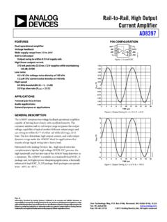
5 * Specified operate values are valid for pulse wave voltage. Please use at rated coil voltage. Please refer to characteristic data and set up adequate voltage in case of use at over voltage. n SAFETY STANDARDS. Type Compliance Contact rating UL UL 508 Flammability: UL 94-V0 (plastics). ANSI/ISA 5A, 277 VAC (resistive). 5A, 30 VDC. E63614, E225300 1/10 HP, 277 VAC /125 VAC. CSA No. 14 Pilot duty: D300, C300, R300. LR 40304. VDE IEC/EN61810-1 5A, 250 VAC, cos 1. CQC 5A 250 VAC. 11001063129, 17001164877. Also conform to UL61010-1, UL61010-2-201, IEC/EN61010-1, IEC/EN61010-2-201 (max. 277 VAC). 3. FTR-K1 SERIES. FTR-MY SERIES. n CHARACTERISTIC DATA. (Characteristic data is not guaranteed value but measured values of samples from production line.)
6 Operate Timing Coil temperature rise Operating range 10 100. 0A. Nominal voltage multiplying factor 9 90. 8 80 3A. 7 70 5A. Time (ms). 6 60. 5 50. 4 Operate 40 Must operate voltage 5A (hot coil). 3 30 3A. 2 Release 20. 1 10 0A Must operate voltage (cool coil). 0 0. 0 0 20 40 60 80 100 120. Coil POWER (W) Coil POWER (W). Maximum switching POWER Life curve 10 500. 300. 5 200 30 VDC/250 VAC resistive 3 AC resistive 100. Contact current (A). Operation (x10 4 ). 2 30 VDC L/R=7ms 50. 30. 1 20. DC resistive 10. 5. 3. 2. 1. 10 20 30 50 100 200 300 500 1 2 3 5 10. Contact voltage (V) Contact current (A). Distribution of operate/relase voltage Distribution of operate/relase time Distribution of contact resistance 100 100 100. Operate voltage FTR-MYAA024D FTR-MYAA024D FTR-MYAA024D.
7 Release voltage n =300 n =300 n =300. 80 80 80. Operate time . Release time Distribution (%). Distribution (%). Distribution (%). 60 60 60. 40 40 40. 20 20 20. 0 20 40 60 80 100 0 2 4 6 8 10 0 10 20 30 40 50. Nominal voltage multiplying factor (%) Time (ms). Mechanical life test Electrical life test Electrical life test 20 20 20. Operate Voltage (V). Operate Voltage (V). Voltage (V). 16 16 16 Operate 12 12 12. 8 8 8. Release Release 4 4 Release 4. Contact resistance (m ). Contact resistance (m ). Contact resistance (m ). 0 0 0. 20 20 20. 10 10 10. 7 7 7. 5 5 5. 3 3 FTR-MYAA024D n=8 3. 2 2 Duty cycle: 1sec. ON/1sec. OFF 2 FTR-MYAA024D n=8. FTR-MYAA024D n=20 Duty cycle: 1sec. ON/1sec. OFF. 1 20Hz (Duty 50%) 1 250 VDC, 3A (resistive) 1.
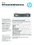
8 30 VDC, 3A (resistive). Initial 5 10 15 20 Initial 10 Initial 10. Operation (x10 6) Operation (x10 4) Operation (x10 4). 4. FTR-K1 SERIES. FTR-MY SERIES. n DIMENSIONS. l Dimensions l Schematics l PC board mounting hole layout (BOTTOM VIEW). Unit: mm * Dimensions of the terminals do not include thickness of pre-solder. * Tolerance of PC board mounting hole layout : unless otherwise specified. 5. FTR-K1 SERIES. FTR-MY SERIES. RoHS Compliance and Lead Free Information 1. General Information l All relays produced by Fujitsu Components are compliant with RoHS directive 2011/65/EU including amendments. l Cadmium as used in electrical contacts is exempted from the RoHS directives. As per Annex III of directive 2011/65/EU. l All relays are lead-free.
9 Please refer to Lead-Free Status Info for older date codes at: l Lead free solder plating on RELAY terminals is , unless otherwise specified. This material has been verified to be compatible with PbSn assembly process. 2. Recommended Lead Free Solder Condition l Recommended solder Flow Solder Condition: Pre-heating: maximum 120 C. within 90 sec. Soldering: dip within 5 sec. at 255 C 5 C solder bath RELAY must be cooled by air immediately after soldering Solder by Soldering Iron: Soldering Iron 30-60W. Temperature: maximum 350-360 C. Duration: maximum 3 sec. We highly recommend that you confirm your actual solder conditions 3. Moisture Sensitivity l Moisture Sensitivity Level standard is not applicable to electromechanical relays, unless otherwise indicated.
10 4. Tin Whiskers l Dipped SnAgCu solder is known as presenting a low risk to tin whisker development. No considerable length whisker was found by our in house test. Cautions * All values mentioned in this datasheet are provided under ideal conditions. Please perform the confirmation test before actual use. * Reflow soldering is prohibited. * Do not use relays in the atmosphere with sulfide gas, chloride gas or nitric oxide. Contact resistance may increase. * Do not use silicon or silicon-containing product or materials near relays. It may cause contact failure. 6. FTR-K1 SERIES. FTR-MY SERIES. Fujitsu Components International Headquarter Offices Japan Asia Pacific Korea Fujitsu COMPONENT LIMITED Fujitsu COMPONENTS ASIA, LTD. Fujitsu COMPONENTS KOREA LIMITED.