Transcription of Power-supply sequencing for FPGAs - TI.com
1 Analog Applications Journal Communications Power-supply sequencing for FPGAs By Sami Sirhan Analog Systems Engineering Sureena Gupta Applications Engineer Introduction Figure 1. Cascading PGOOD pin into enable pin Power-supply sequencing is an important aspect to con- sider when designing with a field programmable gate array (FPGA). Typically, FPGA vendors specify power -sequenc- VIN. ing requirements because an FPGA can require anywhere VOUT1. from three to over ten rails. By following the recommended power sequence, exces- VOUT2. TPS62085. sive current draw during startup can be avoided, which in TPS62085. turn prevents damage to devices. sequencing the power EN. supplies in a system can be accomplished in several ways. PGOOD EN. This article elaborates on sequencing solutions that can be implemented based on the level of sophistication needed by a system.
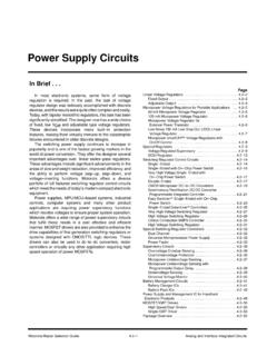
2 sequencing solutions addressed in this article are: 1. Cascading PGOOD pin into enable pin 2. sequencing using a reset IC Method 2: sequencing using a reset IC. 3. Analog up/down sequencers Another simple option to consider for power -up sequenc- 4. Digital system health monitors with PMBus interface ing is a reset IC with time delay. With this option, the reset IC monitors the power rails with tight threshold limits. Method 1: Cascading PGOOD pin into enable pin Once the power rail is within 3% or less of its final value, A basic, cost-effective way to implement sequencing is to the reset IC enters the wait period defined by the solution cascade the power good (PG) pin of one power supply before powering up the next rail. The wait period can be into the enable (EN) pin of the next sequential supply programmed into the reset IC using EEPROM or be set by (Figure 1).
3 The second supply begins to turn on when the external capacitors. A typical multi-channel reset IC is PG threshold is met, usually when the supply is at 90% of shown in Figure 2. The advantage of using a reset IC for its final value. This method offers a low-cost approach, but power -up sequencing is that the solution is monitored. timing cannot be eas- ily controlled. Adding Figure 2. power -up sequencing with a multi-output reset IC. a capacitor to the EN. pin can introduce tim- ing delays between VIN DC/DC LDO. VCC4. stages. However, this VCC3. method is unreliable DC/DC LDO VCC2. during temperature EN4. EN. VCC1. variations and repeated VCC. power cycling. DC/DC LDO. TPS386000 VCC1 VCC2 VCC3 VCC4. SENSE1 RESET1 RESET DSP. Also, this method EN3 EN SENSE2 RESET2 CPU.
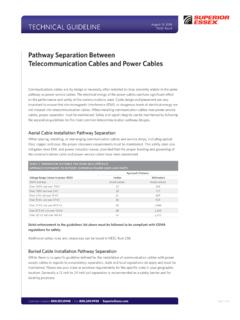
4 Does not support Dividers SENSE3 FPGA. RESET3. power -down DC/DC LDO CLK. EN2 SENSE4L RESET4. sequencing . EN. SENSE4H WDI. CT1 CT2 CT3 CT4 GND. CT1 CT2 CT3 CT4. Sequence: VIN VCC4 VCC3 VCC2 VCC1. texas instruments 19 AAJ 4Q 2014. Analog Applications Journal Communications Each rail is confirmed to be within regulation before Figure 3. Implementation of an releasing the next rail and there is no need for a PGOOD. analog up/down sequencer pin on the power converter. The drawback of using a reset-IC solution for sequencing is that it does not imple- Input ment power -down sequencing . supply Device 1. Method 3: Analog up/down sequencers VCC. Implementing power -up sequencing can be easier than LM3880. Enable implementing power -down sequencing . To achieve power - up and power -down sequencing , there are simple analog FLAG 1 Device 2.
5 Enable sequencers (Figure 3) that can reverse (Sequence 1) or EN. FLAG 2 Enable even mix (Sequence 2) the power -down sequence relative FLAG 3. to the power -up sequence. Upon power up, all the flags Device 3. are held low until EN is pulled high. After EN is asserted, GND. each flag goes open drain (pull-up resistor is required) Enable sequentially after an internal timer has elapsed. The power -down sequence is the same as power up, but in reverse order. Input EN. Cascading multiple sequencers Sequence 1. FLAG1. Sequencers can be cascaded together to support many Output power rails, as well as provide fixed and adjustable delay FLAG2. times between enable signals. In Figure 4, two sequencers FLAG3. cascade together to achieve six sequenced rails.
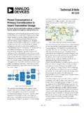
6 Upon Delay1. Delay2. Delay3. Delay4. Delay5. Delay6. power up, the AND gate ensures that the second sequencer does not trigger until it has received both an Sequence 2. FLAG1. EN signal and rail C has triggered. On power down, the FLAG2. AND gate ensures that the second sequencer sees the EN. falling edge, irrespective of output C. The OR gate ensures FLAG3. that the first sequencer is triggered with the EN rising edge. Upon power down, the OR gate ensures that the first sequencer can't see the EN falling edge until D has fallen. This guarantees power -up and power -down Figure 4. Cascading multiple analog sequencers sequencing , but does not offer a monitored sequence. Monitored up/down sequencing Rails Monitored sequencing can be added to the circuit in LM3880 A.
7 #1. Figure 4 by simply adding a couple of AND gates between EN. B. the FlagX output and the PG pin as shown in Figure 5. In EN C. this example, PS2 is enabled only if PS1 is greater than 90% of its final value. This method offers a low-cost, moni- LM3880 D. tored sequencing solution. #2 E. EN F. Method 4: Digital system health monitors with PMBus interface If a system requires the utmost flexibility, a good solution is a PMBus/I2C-compatible, digital-system health monitor such as the UCD90120A. Such solutions offer maximum Figure 5. Adding monitored sequencing to a control for any sequencing need by allowing the designer simple time-based sequencer to configure ramp up/down times, on/off delays, sequence dependencies, and even voltage and current monitoring.
8 FLAG1. PS1. Dual AND. FLAG2. LM388x PS2. PWRGD PS1. FLAG3. PWRGD PS2 PS3. texas instruments 20 AAJ 4Q 2014. Analog Applications Journal Communications Figure 6. Example of power up sequencing using the UCD90120A GUI. Digital-system health monitors come with a graphical Figure 7. Example of a FPGA. user interface (GUI) that can be used to program power - power -logic sequence up and power -down sequencing along with other system parameters (Figure 6). Some digital system health moni- tors also have non-volatile-error and peak-value logging Block that helps with system-failure analysis in case of a brown- Core Auxiliary I/O. RAM. supply supply Supplies out event. supply FPGA sequencing requirements examples FPGA vendors such as Xilinx or Altera provide either a recommended or required power -up sequence in their Related Web sites datasheets that are easily accessible online.
9 sequencing requirements vary between vendors and vary from one vendor's FPGA family to another. Also listed in datasheets are timing requirements for ramp-up and shutdown. The recommended power -down sequence is typically the reverse order of the power -up sequence. An example of power -up sequencing is shown in Figure 7. Subscribe to the AAJ: Conclusion There are several sequencing solutions that can be utilized to follow the requirements specified by FPGA vendors. System requirements may include power monitoring in addition to power -up and power -down sequencing , but the optimal power solution for an FPGA will depend on sys- tem complexity and specifications. texas instruments 21 AAJ 4Q 2014. Analog Applications Journal TI Worldwide Technical Support Internet TI Semiconductor Product Information Center Home Page TI E2E Community Home Page Product Information Centers Americas Phone +1(512) 434-1560 Asia Phone Toll-Free Number Brazil Phone 0800-891-2616.
10 Note: Toll-free numbers may not support Mexico Phone 0800-670-7544 mobile and IP phones. Australia 1-800-999-084. Fax +1(972) 927-6377 China 800-820-8682. Internet/Email Hong Kong 800-96-5941. India 000-800-100-8888. Europe, Middle East, and Africa Indonesia 001-803-8861-1006. Phone Korea 080-551-2804. European Free Call 00800-ASK- texas Malaysia 1-800-80-3973. (00800 275 83927). New Zealand 0800-446-934. International +49 (0) 8161 80 2121. Philippines 1-800-765-7404. Russian Support +7 (4) 95 98 10 701. Singapore 800-886-1028. Taiwan 0800-006800. Note: The European Free Call (Toll Free) number is not active in all countries. If you have technical difficulty calling the free call Thailand 001-800-886-0010. number, please use the international number above.