Transcription of Practical Guide to Implementing Solar Panel MPPT Algorithms
1 2013 Microchip Technology 1AN1521 INTRODUCTIONU sing a Solar Panel or an array of panels without acontroller that can perform Maximum power PointTracking (MPPT) will often result in wasted power ,which ultimately results in the need to install morepanels for the same power requirement. Forsmaller/cheaper devices that have the batteryconnected directly to the Panel , this will also result inpremature battery failure or capacity loss, due to thelack of a proper end-of-charge procedure and highervoltage. In the short term, not using an MPPT controllerwill result in a higher installation cost and, in time, thecosts will escalate due to eventual equipment with a proper charge controller , the prospect ofhaving to pay 30-50% more up front for additional solarpanels makes the MPPT controller very application note describes how to implementMPPT using the most popular switching power supplytopologies.
2 There are many published works on thistopic, but only a tiny portion of them show how toactually implement the Algorithms in hardware, as wellas state common problems and pitfalls. Even whenusing the simplest MPPT algorithm with awell-designed synchronous switching power supply, itcan be expected that at least 90% of the Panel savailable power will end up in the battery, so thebenefits are topology presented in this application note is aninverse SEPIC, but the techniques used here can beapplied to buck, boost and SEPIC converters. The buckconverter is a special case, since it has a linear voltagetransfer function when operating in ContinuousConduction Mode (CCM).
3 This simplifies things a lot,and the MPPT controller can be implemented byoperating directly on the converter duty cycle. Theother topologies have a nonlinear voltage transferfunction, and operating directly on the duty cycle willyield unpredictable results, especially at high dutycycles. In this case, the algorithm modifies the solarpanel operating voltage by using a proportional integral(PI) control loop, which steers the voltage to thedesired Panel MPPTThe main problem solved by the MPPT Algorithms is toautomatically find the Panel operating voltage thatallows maximum power output. In a larger system,connecting a single MPPT controller to multiple panelswill yield good results, but, in the case of partialshading, the combined power output graph will havemultiple peaks and valleys (local maxima).
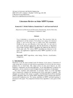
4 This willconfuse most MPPT Algorithms and make them trackincorrectly. Some techniques to solve problems relatedto partial shading have been proposed, but they eitherneed to use additional equipment (like extra monitoringcells, extra switches and current sensors for sweepingpanel current), or complicated models based on thepanel characteristics ( Panel array dependent). Thesetechniques only make sense in large Solar panelinstallations, and are not within the scope of thisapplication , each Panel or small cluster of panels shouldhave their own MPPT controller . This way the risk ofpartial shading is minimized, each Panel is allowed tofunction at peak efficiency, and the design problemsrelated to converters handling more than 20-30A typical Solar Panel power graph (Figure 1) shows theopen circuit voltage to the right of the maximum powerpoint.
5 The open circuit voltage (VOC) is obviously themaximum voltage that the Panel outputs, but no poweris drawn. The short-circuit current of the Panel (ISC) isanother important parameter, because it is the absolutemaximum current you can get from the Panel . Authors: Mihnea Rosu-HamzescuSergiu OpreaMicrochip Technology Guide to Implementing Solar Panel MPPT AlgorithmsAN1521DS00001521A-page 2 2013 Microchip Technology 1: Solar Panel CHARACTERISTICS 2013 Microchip Technology 3AN1521 The literature on this subject generally agrees that themaximum amount of power that can be extracted froma Panel depends on three important factors: irradiance,temperature and Panel and load impedances with a DC-DCconverter makes sense, because for example, if youhave a 5V/2A load, and a 20W Panel that has the MPPat , connecting the load directly will notwork.
6 Considering a simple resistive load, and theshort-circuit current of , the Panel will only be ableto provide about 3 , or less than 4W out of 20W. Temperature mainly changes the Panel voltageoperating point, while irradiance mainly changes thepanel operating current. Figure 1 shows the effect ofdifferent irradiance levels on the Panel voltage, currentand are a few MPPT Algorithms that can be easilyimplemented using an 8-bit OPEN CIRCUIT VOLTA GEThe maximum power point voltage has a lineardependency on the open circuit voltage VOC underdifferent irradiance and temperature the MPP (Maximum power Point) comesdown to:EQUATION 1:The constant k depends on the type and configurationof the photovoltaic Panel .
7 The open circuit voltage mustbe measured and the MPP determined in some way fordifferent ambient conditions. Usually, the systemdisconnects the load periodically to measure VOC andcalculate the operating voltage. This method has someclear disadvantages, temporary loss of power being anobvious one. An alternate method would be to use oneor more monitoring cells, but they also need to bechosen and placed very carefully to reflect the trueopen circuit voltage of the this method is quite simple and robust anddoes not require a microcontroller, the constant onlyallows a crude approximation of the MPP. Otheralgorithms will significantly increase the top powerdrawn from the same PV SHORT CIRCUIT CURRENTThe MPP can also be determined from the short-circuitcurrent of the Panel (ISC), because IMPP is linearlyrelated to it under varying atmospheric 2:Similar to fractional open circuit voltage, the constantmust be determined for each type of ISC is more challenging, because doing sofrom time to time not only increases power loss andheat dissipation, but also requires an additional switchand current sensor.
8 Obviously, this increasescomponent count and cost. The simplestimplementations do not require microcontrollers, but forbetter accuracy and to solve problems related to partialshading, more processing power is necessary tosweep the Panel current from 0 to ISC, and memorizethe output voltage =IMPPkIISC=AN1521DS00001521A-page 4 2013 Microchip Technology AND OBSERVE (P&O)FIGURE 2:P&O ALGORITHMP&O is one of the most discussed and used algorithmsfor MPPT. The algorithm involves introducing aperturbation in the Panel operating voltage. Modifyingthe Panel voltage is done by modifying the converterduty cycle. The way this is done becomes important forsome converter at Figure 2 makes it easy to understand thatdecreasing voltage on the right side of the MPPincreases power .
9 Also, increasing voltage on the leftside of the MPP increases power . This is the main ideabehind P& s say that, after performing an increase in the paneloperating voltage, the algorithm compares the currentpower reading with the previous one. If the power hasincreased, it keeps the same direction (increasevoltage), otherwise it changes direction (decreasevoltage). This process is repeated at each MPPtracking step until the MPP is reaching the MPP, the algorithm naturallyoscillates around the correct basic algorithm uses a fixed step to increase ordecrease voltage. The size of the step determines thesize of the deviation while oscillating about the a smaller step will help reduce the oscillation,but will slow down tracking , while having a bigger stepwill help reach MPP faster, but will increase power losswhen it be able to implement P&O MPPT, the applicationneeds to measure the Panel voltage and current.
10 Whileimplementations that use only one sensor exist, theytake advantage of certain hardware specifics, so ageneral purpose implementation will still need operatingvoltageIncrease operatingvoltagePk > Pk-1?Pk > Pk-1?Pk = Current power readingPk-1 = Previous power reading 2013 Microchip Technology 5AN1521 INCREMENTAL CONDUCTANCEFIGURE 3:INCCOND ALGORITHMThe incremental conductance algorithm uses the factthat the Panel power curve derivative (or slope) versusvoltage is 0 at MPP, positive on the left side andnegative on the right side of the 3:The power derivative can be also written as:EQUATION 4:So the first bundle of equations (1) can be rewritten as:EQUATION 5:The main idea is to compare the incrementalconductance ( ) to the instantaneous conductance( ).