Transcription of Pressure Reducing Valves - flomatic.com
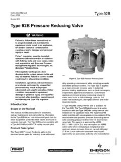
1 Automatic Hydraulic Control ValvesPressure Reducing ValvesSERIES C100/CF100 Ductile IronFlomatic ValvesHiqh Quality Valves Built to to see: Hydraulic Check Valves in our Online Catalog1. Reduce Pressure to a distribution system when supplying by gravity from a source with a relatively high Reduce Pressure to a low Pressure zone when the source is a high lift Reduce Pressure to a lower constant, Pressure within an industrial facility when the municipal supply is the sole source or when supplying emergency water to a plant which loses its primary Reduce Pressure to a low Pressure zone when a high Pressure zone is the sole source or when makeup water is required to supplement the normal supply to the low Pressure Reduce Pressure to the nozzles of an irrigating system when the source is a high Pressure booster C100/CF100 Pressure Reducing VALVESfor Water Systems - Municipal, Industrial and IrrigationThe Pressure Reducing Valve is used to reduce an undesired high upstream (inlet)
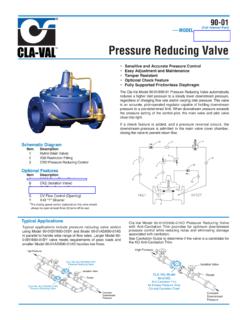
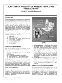
2 Pressure to a constant lower downstream(outlet) operating Pressure regardless of varying upstream (inlet) Pressure and fl ow rates. This series is also available in a reduced cavtation model CF, which has a smaller valve seat APPLICATIONS2 FLOMATIC Pressure Reducing ValveModel No. C101/CF101 Fig. 2 - Single Valve installed horizontal with a manual service by-passshows a service bypass or set up for easy servicing of of Operations The Model No. C101/CF101 Pressure Reducing Valve controlsand maintains a preset, reduced downstream (outlet) Pressure bycausing the main valve to throttle and sustain the desired reduced Pressure regardless of variations in demand and upstream (inlet) Pressure .
3 The throttled position of the main valve is controlled by an adjustable pilot valve (Fig. 1 #4) operating in conjunction with an orifice ( #3). The pilot valve senses the downstream (outlet) Pressure and reacts immediately to reposition the valve as the outlet Pressure tends to increase or decrease with varying demand. The change in throttled position of the pilot valve causes the main valve to reposition and throttle to maintain the preset outlet 3- Dual Valve Installation with service by-pass Fig. 3 - A dual or compound valve installation is recommended when the normal and low flow requirements are considerably lower than peak or fire flows.
4 The by-pass valve is set 5 psi higher than the main valve. Under low flow conditions the main PRP closes and the bypass stays open. Thus controlling the Pressure at low Reduces single valve maintenance costs and minimizes noise, both of which would result from a single large (oversized) valve operating at lower Maintains a more stable Pressure by eliminating or minimizing up- stream (inlet) and downstream (outlet) Pressure fluctuations resulting from hunting action caused by a single large valve at low Insures a continuous supply of reduced Pressure water when one of the Reducing Valves is being Isolation Valve 4.
5 PRP Pilot Valve2. Y Strainer 5. Flow Control3. Orifice (restriction fitting)3 Fig. 1 Fig. 2 ClosedBy-pass ValveFig. 3 FLOMATIC Pressure Reducing Valve with Dual Pilots Model No. C102/CF102 The Model No. C102/CF102 is the same as the Model No. C101 with the addition of a second Pressure Reducing pilot valve. This second pilot permits uninterrupted flow while servicing one of the pilots as well as the ability to easily change to a different reduced Pressure setting. Switching from one pilot to the other may be done manually or Isolation Valve 4. PRP Pilot Valve2. Y Strainer 5. Flow Control3. Orifice (restriction fitting)4 Fig.
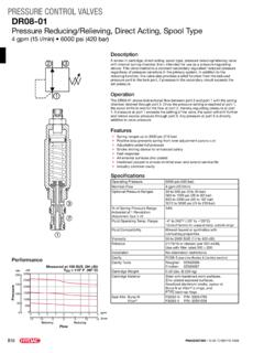
6 4 FLOMATIC Pressure Reducing and Check ValveModel No. C103/CF103 The Model No. C103/CF103 Pressure Reducing and Check Valve provides Pressure reduction plus a check valve feature which causes the valve to close when the downstream (outlet) Pressure is greater than the upstream (inlet) Isolation Valve 4. PRP Pilot Valve2. Y Strainer 5. Check Valve3. Orifice (restriction fitting) 6. Flow ControlFig. 5 FLOMATIC Pressure Reducing and Back Pressure Sustaining ValveModel No. C104/CF104 The Model No. C104/CF104 Pressure Reducing and Back Pressure Valve provides Pressure reduction plus back Pressure control which sustains aminimum upstream (inlet) Pressure .
7 After the upstream (inlet) Pressure is safely achieved the Pressure Reducing feature maintains a preset downstream Pressure . 1. Isolation Valve 4. BPP Pilot Valve2. Y Strainer 5. PRP Pilot Valve3. Orifice (restriction fitting) 6. Flow ControlFig. 6 FLOMATIC Pressure Reducing , Back Pressure Sustaining and Check Valve Model No. C104-C/CF104-CThe Model No. C104-C/CF104-C Pressure Reducing , Back Pressure and Check Valve combines the control features of Model No. C103/CF103 and C104 valve provides a reduced downstream Pressure , sustains a minimum upstream Pressure and closes to prevent reverse flow if the downstream Pressure becomes greater than the upstream Isolation Valve 5.
8 BPP Pilot Valve2. Y Strainer 6. PRP Pilot Valve3. Check Valve 7. Flow Control4. Orifice (restriction fitting)Fig. 7 FLOMATIC Pressure Reducing and Back PressureSustaining Valve with Solenoid OverrideModel No. C104-S/CF104-SFLOMATIC Pressure Reducing Valve with Solenoid OverrideModel No. C105/CF105, C106/CF106 and C107/CF107 FLOMATIC Pressure Reducing Valve with Open Wide ControlModel No. C108/CF108 The Model No. C104-S/CF104-S Pressure Reducingand Back Pressure Valve with solenoid override providesdownstream Pressure reduction and upstream back pressurecontrol when a two-way, normally open solenoid pilotis de-energized (or when a two-way normally closed solenoidpilot is energized).
9 Energizing the normally open solenoid pilot or de-energizingthe normally closed solenoid pilot closes Isolation Valve 5. BPP Pilot Valve2. Y Strainer 6. Solenoid Valve3. Orifice (restriction fitting) 7. Flow Control4. PRP Pilot ValveThe Model No. C105/CF105 permits flow and provides pressurereduction when the two-way, normally open solenoid control is the solenoid control closes the valve. The Model No. C106/CF106 permits flow and provides pressurereduction when the two-way, normally closed solenoid control is the solenoid control closes the Model No. C107/CF107 provides Pressure reduction when thethree-way solenoid control is de-energized.
10 Energizing the solenoid controlcauses the valve to open Isolation Valve 4. PRP Pilot Valve2. Y Strainer 5. Solenoid Valve3. Orifice (restriction fitting) 6. Flow ControlThe Model No. C108/CF108 normally provides Pressure , if the upstream (inlet) Pressure drops to a preset lower value, asecondary hydraulic control pilot is actuated to cause the valve to openwide for maximum Isolation Valve 4. PRP Pilot Valve2. Y Strainer 5. Under Pressure Pilot3. Orifice (restriction fitting) 6. Flow ControlInformation Required with Valve Order1. Size 4. Paint Specification 7. Maximum and Minimum Flow Rates2.