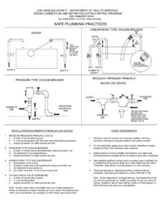
Transcription of Reduced Pressure Zone Valve Installation Instructions
1 Reduced Pressure Zone Valve Installation Instructions Model RPZ 2-1/2 10 Flomatic Corporation Flomatic Corp, 15 Pruyn s Island, Glens Falls, New York 12801 Phone: 518-761-9797 Fax: 518-761-9798 June 2006 Rev. D (5/11) RPZ Basic Installation Instructions : CAUTION: lnstallation of backflow Preventers must be performed by qualified, licensed personnel. Faulty Installation could result in an improperly functioning assembly. The installer should be sure the proper assembly has been selected for the particular Installation . The Flomatic Model RPZ Reduced Pressure Principle backflow Preventers are for use on potable water lines where a health hazard could exist if a backflow or back-siphonage situation were to occur.
2 Proper performance is dependent upon following these Installation Instructions and prevailing governmental and industry standards and codes. Failure to do so, according to Flomatic Corporations Limited Warranty "releases Flomatic Corporation of any liability that it might otherwise have with respect to that assembly". Such failure could also result in an improperly functioning assembly. Damage to the assembly could result wherever water hammer and/or water thermal expansion could create excessive line Pressure . Where this could occur, shock arrestors and/or Pressure relief valves should be installed downstream of the assembly.
3 1. Before installing a Model RPZ backflow Preventer, flush the lines thoroughly to remove all debris, chips and other foreign matter. If required a strainer should be placed upstream of the backflow Preventer. CAUTION: Do not use a strainer in seldom used emergency water lines such as fire lines. 2. The Model RPZ must be installed in a horizontal or vertical position with flow down to provide proper operation of the relief Valve . 3. Provide adequate space around the installed unit so that the test cocks will be accessible for testing and servicing. 4. If Installation of a Model RPZ unit is in a building, provide a suitable drain arrangement to drain off spillage from the relief Valve .
4 An air gap of at least two times the pipe diameter must be provided between the relief Valve and the drain piping to prevent a cross connection. CAUTION: Do not pipe the relief Valve solidly to a floor drain, sewer or sump. 5. Install Valve at least 12 inches above surrounding flood level. 6. Always consult local codes for Installation methods, approvals and guidelines. Outdoor Installation Models RPZ backflow Preventers may be installed outdoors only if the assembly is protected against any freezing conditions. Exposure to freezing conditions will result in improper function or damage to the assembly.
5 The Installation location must be kept above 32o F. All the basic Installation Instructions apply. If Installation is in a pit or vault, the backflow preventer must never be submerged in water because this could cause a cross-connection. Make sure that the pit or vault always remains dry by providing ample drainage. Indoor Installation Indoor Installation is preferred in areas that are subject to freezing conditions. All the basic Installation Instructions apply to such installations. Parallel Installation Where uninterrupted service from a single meter connection must be maintained, two or more backflow Preventers may be connected in parallel.
6 All the basic Installation Instructions apply to a parallel Installation . Be sure to allow adequate room between the units for testing and repair. Reduced Pressure Zone Valve Installation Instructions Model RPZ 2-1/2 10 Flomatic Corporation Flomatic Corp, 15 Pruyn s Island, Glens Falls, New York 12801 Phone: 518-761-9797 Fax: 518-761-9798 June 2006 Rev. D (5/11) RPZ STEMSPRINGSPRING RETAINERDO NOT DISASSEMBLEDISC HOLDERDISC RETAINERDISCSEAT RINGO-RINGP lacing the Assembly in Service After the Installation of a Model RPZ unit has been completed, place the unit in service as follows: 1.
7 Start with both shut-off valves closed. Slowly open the inlet shut-off Valve until the backflow preventer is completely pressurized. 2. A brief discharge from the relief Valve may occur while the assembly is pressurizing. The discharge should cease by the time the shut-off Valve is fully open. 3. If the discharge does not stop, refer to "Maintenance Instructions " for Repair Procedures. 4. After the assembly has been pressurized, vent all trapped air from both check valves and the relief Valve by slightly opening each of the four test cocks. 5. Slowly open the downstream shut off Valve .
8 The Model RPZ Reduced Pressure Principle backflow Preventer is now in service. 6. If spitting or intermittent discharges from the relief Valve are noted, spitting (drainage) from the relief Valve could be a result of Pressure fluctuations and/or water hammer condition in the system. If such condition exists, install water Pressure reducing valves or water hammer shock arrestors in compliance with industry standards as needed. 7. After the backflow preventer has been properly installed, test the assembly (see Test Procedures). If the assembly fails the test, remove the first and second check valves and thoroughly flush the assembly.
9 If the relief Valve fails to operate properly, inspect the sensing passage for clogging (also see maintenance Instructions ). Clean rubber seats of all debris and place unit back in service. MAINTENANCE Instructions 1. GENERAL A. Clean all parts thoroughly with water after disassembly. B. Carefully inspect silicone discs, and o-rings for damage. C. Test unit after reassembly for proper operation. 2. SERVICING CHECK valves A. Close inlet and outlet shut-off valves . B. Open #2, 3, and 4 test cocks to release Pressure from Valve . C. Remove the cover bolts & Valve cover. CAUTION: COVER IS SPRING LOADED.
10 To avoid injury, hold cover down firmly with one hand while loosening bolts. D. Remove relief Valve cover and assembly. E. Remove the check Valve spring clips. F. Remove the 1st check Valve assembly. G. Remove the 2nd check Valve assembly. H. Inspect check Valve seat and o-ring for debris and damage. I. To remove silicone disc, unscrew check Valve stem from disc holder. J. Remove disc retainer and disc from the disc holder and inspect for cuts or embedded debris. K. The silicone disc may be inverted if the reverse side is undamaged. L. Inspect the Valve cavity and seat area for damage and debris.