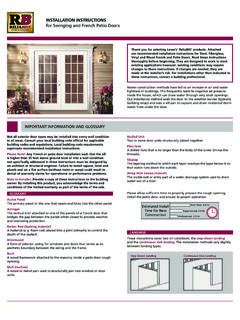
Transcription of Swing Check Valve Installation Instructions
1 Flomatic Corp, 15 Pruyn s Island, Glens Falls, New York 12801 Phone: 518-761-9797 Fax: 518-761-9798 745 Rev. F February 12, 2019 O&M Manual Flo-Flex Swing Check Valve Model 745 Operation, Maintenance and Installation Manual FAILURE TO FOLLOW THESE INSTRUCTION WILL VOID ANY WARRANTY Note: Keep this O&M Manual in a safe place for future reference for service and parts. Model: _____ Size: _____ Type: _____ Working Pressure: _____ Installation Date: _____ Flomatic Corp, 15 Pruyn s Island, Glens Falls, New York 12801 Phone: 518-761-9797 Fax: 518-761-9798 745 Rev. F February 12, 2019 FLOMATIC FLO-FLEX Swing Check Valve Operation, Maintenance and Installation Manual INTRODUCTION The Flomatic Flo-Flex Model 745 Swing Check Valve has been designed to give years of trouble-free operation during normal operation.
2 This O&M owners manual will provide you with the information you need to properly install and maintain the Valve and to ensure a long service life. The Flo-Flex Check Valve is opened automatically by the fluid flow in one direction and closes automatically to prevent back-flow in the reverse direction (see flow arrow cast into the Valve body for flow direction). The Flo-Flex Model 745 Swing Check is design to meet the flange to flange laying length according to AWWA C508. The Valve angled Valve seat and fully encapsulated, resilient disc, is capable of handling a wide range of fluids including flows containing suspended solids.
3 Flomatic can provide an optional manual back-flush device that can be installed on the bottom of the Valve to allow manual backflow through the Valve in the reverse direction (Option Model 745 BF ). Optional Position Indicators (Option Model 745 PI ) PI and Limit Switches (Option Model 745 LS ) may also be mounted on the Valve access cover to provide position indication. The Valve Size, Flow Direction, Maximum Working Pressure are cast on to the side of the Valve body surface for reference. The "Maximum Working Pressure" is the non-shock pressure rating of the Valve at Max Temperature of 140 F (60 C).
4 The Valve shall not be subjected to any higher pressure or temperature above the Valve maximum standard rating. RECEIVING AND STORAGE Inspect valves upon receipt for damage in shipment. Unload Valve carefully to the ground without dropping. Do not allow lifting slings or chains to come in contact with the seat or flange sealing surface area; use eyebolts or rods through the flange holes on large valves . valves should remain crated, clean and dry until installed to prevent weather related damage. For long term storage greater than six months, the rubber surfaces of the disc should be coated with a thin film of FDA approved grease such as Super Lube.
5 Do not expose disc to sunlight or ozone for any extended period as elastomer will get damaged and degraded. DESCRIPTION OF Valve OPERATION The Valve is designed to prevent reverse flow automatically. During system flow conditions, the movement of the fluid forces the disc to the open position allowing 100% flow area through the Valve . The valves rubber coated steel disc automatically returns to the closed position to prevent reverse flow. Several optional features are a Backflush device, (Model 745 BF), Position Indicator (Model 745PI), Limit Switch (Model 745LS). These Valve product options are described in more details below.
6 Valve CONSTRUCTION The Flomatic Flo-Flex Swing Check Valve is constructed of rugged Ductile Iron with a rubber encapsulated Valve disc. The rubber coated Valve disc is the only moving part assuring long life with minimal maintenance. The general details of construction are illustrated in Fig. 2. The body (1) is flanged for connection to the pipeline with an access cover (2). The disc (3) is retained by the cover. Item # Qty. Description Material ASTM 1 1 Body Ductile Iron A536 2 1 Cover Ductile Iron A536 3 1 Disc* Buna coated Steel -------- 4 1 Gasket Buna -------- 5 A/R Cover Bolt Steel SAE Grade 5 6 1 Plug Malleable Iron -------- *Optional EPRM or Viton Coated Steel Standard Max Working Pressure: 2 thru 24 250 psi Standard Max Temperature: 140 F (60 C) FIG 1.
7 Flo-Flex Swing Check Valve Fig 2. Flo-Flex Cross Section Flomatic Corp, 15 Pruyn s Island, Glens Falls, New York 12801 Phone: 518-761-9797 Fax: 518-761-9798 745 Rev. F February 12, 2019 Installation Correct Installation of the Flomatic Flo-Flex is important for proper operation. It may be installed in either horizontal or vertical flow-up applications. Horizontal Installation , with the access port facing up is recommended for waste water application as it will prevent material in the fluid to collect on the Valve disc. In all installations, the flow arrow cast in the Valve and cover must be pointed in the direction of flow.
8 Flanged valves should only be mated with flat-faced pipe flanges equipped with full-face resilient gaskets. The Valve and adjacent piping must be supported and aligned to prevent cantilevered stress on the Valve . Once the flange bolts or studs are lubricated and inserted around the flange, tighten them uniformly hand tight. The tightening of the bolts should then be done in graduated steps using the crossover tightening method. Recommended lubricated torque values for use with resilient gaskets (75 durometer) are given in Table 1. If leakage occurs, allow gaskets to absorb fluid and Check torque and leakage after 24 hours.
9 Do not exceed bolt rating or the flange gasket can get damaged and extrude. TROUBLESHOOTING Below are some potential problems with solutions to assist you in troubleshooting the Valve assembly in a safe manner. Also, visit Flomatic web page for technical product references and parts lists or call customer service 1-800-833-2040. MAINTENANCE The Flomatic Flo-Flex Swing Check Valve requires no scheduled lubrication or maintenance. For service or inspection, the valves internal parts can be accessed and serviced without removal from the line. WARNING: The line must be drained and de-pressurized before removing the cover or the bottom plug if not this may cause bodily harm.
10 Valve INSPECTION: DISASSEMBLY & RE-ASSEMBLY The valves internal parts can be disassembled and serviced without removing it from the pipeline. All service and repair work performed on the Valve shall be performed by a skilled mechanic with proper tools and a power hoist for larger valves . It is recommended that when disassemble the Valve to inspect the rubber Valve disc for wear or the Valve seat for deposits. Dimensions for 150# Class valves Max Torque Valve Size Flange Outside Diameter Number of Bolt Holes Bolt Diameter 150# 300# (inches) (inches) (inches) ( ) ( ) 2 6 4 5/8 90 90 2-1/2 7 4 5/8 90 150 3 7-1/2 4 5/8 90 150 4 9 8 5/8 90 150 6 11 8 3/4 150 150 8 13-1/2 8 3/4