Transcription of Product Bulletin: 92B Pressure Reducing Valve - Emerson
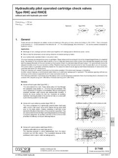
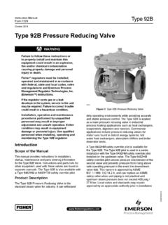
1 Bulletin :92 BSeptember 92B Pressure Reducing Valve Extended Diaphragm Service Life Two-Path Control Elevated Actuator Resilient Seats Bellows Stem Guide Double Post Stem Guide Standard ANSI Face-to-Face LifeFigure 1. Type 92B Pressure Reducing ValveW8264 Bulletin :92B2 IntroductionThe Type 92B Pressure Reducing Valve is the standard steam Valve for industry. The Type 92B is designed to provide decades of continuous service. It can withstand dirty operating environments while providing accurate and stable Pressure control. The Type 92B is applied as a main Pressure Reducing Valve in industrial process heating applications such as heat exchangers, evaporators, digesters and reactors. Commercial applications include Pressure Reducing valves for meter runs found in district energy systems, hot water heat exchangers, absorption chillers and boiler deaerator Type 92B is rated for inlet Pressure up to 300 psig / bar and inlet temperatures to 600 F / 316 C.
2 Maximum controlled outlet Pressure is 250 psig / bar. A large actuator and heavy main spring ensures high accuracy and stability over its entire steam flow safety override pilot is available for the Type 92B Pressure Reducing Valve . The Type 92B pilot is used in a series installation with the Type 6492HM safety override pilot installed on the upstream Valve . The Type 6492HM safety override pilot senses Pressure downstream of the second Valve and prevents Pressure from rising above safe operating Pressure in the event the downstream Valve fails. This system is approved by ASME , and can replace an ASME safety Valve when vent piping is not practical and upstream steam Pressure does not exceed 400 psig / bar. Local codes and standards may require approval by an appropriate authority prior to 2.
3 Typical Type 92B ConstructionFeatures Extended Diaphragm Service Life Two-ply construction and dual flex points increases cycle life compared to conventional designs. Stainless steel material ensures satisfactory operation at high steam temperatures. Resilient Seats Valve seats are individually lapped for tight shutoff. Beveled seats ensure easy in-line lapping. Plug and Valve seats are constructed of hardened stainless steel which reduces wire drawing in wet steam applications. Standard ANSI Face-to-Face NPT, CL125 FF, CL150 RF, CL250 RF and CL300 RF end connections are ANSI standard face-to-face dimensions. The Type 92B main Valve is also available with PN 16/25/40 RF end connections. Bellows Stem Guide Pilot bellows reduces sticking from scale build-up due to boiler is a mark owned by Special Metals Corporation.
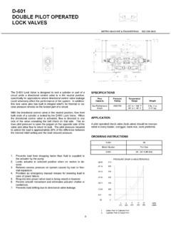
4 Elevated Actuator Plugging from scale and rust is reduced as condensate will not pool in critical areas. Two-Path Control Downstream Pressure registers under main Valve and pilot diaphragms improving response time. Double Post Stem Guide Top and bottom seat guides with Inconel bushings eliminate lateral plug instability and premature stem :92B3 Figure 2. Typical Type 92B ConstructionPIPE PLuG oR TuBE FITTING - DIRECTLy ovER oRIFICE FoR EASEoF ACCESSIBILITyBLEED oRIFICE - EASILyCLEANED wITh wIREDIAPhRAGmS ANDDIAPhRAGm PLATEDIAPhRAGmS CASEGuIDE BuShINGPILoT SPRING CASEPILoT PRESSuRESETTING SPRINGBELLowS ANDBELLowS RETAINERLowER SPRING SEAToRIFICEChECk Valve ASSEmBLyPILoT Valve STEmAND PLuGvALvE STEm GuIDEPILoT Valve SPRINGvALvE PLuGAND SEAT RINGREDuCING Valve SPRINGBoTT om FLANGEB ulletin :92B4 SpecificationsThis section lists the specifications for the Type 92B Pressure Reducing Valve .
5 The following information is stamped on the nameplate of Type 92B: Type Number, Maximum Outlet Pressure , Maximum Inlet Pressure and Maximum Configurations Pilot-operated globe-style Pressure Reducing Valve with post guiding and flow-to-close Valve plug Sizes and End Connection Styles See Table 1 Body Ratings and maximum Inlet Pressures(1) See Table 3minimum Differential Pressures Required for Full Stroke(1) 20 psig / bar with Stainless steel spring; 10 psig / bar with Inconel springmaximum outlet (Casing) Pressure Cast iron: 150 psig / bar or body rating limits, whichever is lower Steel/Stainless steel: 300 psig / bar or body rating limits, whichever is loweroutlet Pressure Ranges(1) See Table 2 Flow Coefficients See Table 5 Flow Capacities See Table 6 Pressure Registration Externalmaximum Temperature Capabilities(1) See Table 3 Downstream Control Line Connections NPS 1 and 1-1/2 / DN 25 and 40: 1/4 NPT NPS 2 / DN 50: 3/8 NPT NPS 3 and 4 / DN 80 and 100: 1/2 NPTA pproximate weights See Table 7 Construction materials main Valve Body, Bottom Flange, Diaphragm Case and Diaphragm Plate.
6 Cast iron, WCC Steel or CF8M Stainless steelConstruction materials (continued) main Valve (continued) Bottom Flange Gasket: Cast iron: Composition; Steel/Stainless steel: Graphite Diaphragms: Stainless steel Valve Plug: 410 or 416 Stainless steel Seat Ring: 416 Stainless steel (standard), 316 Stainless steel (seal weld option) Valve Plug Guide Bushing: 17-4PH Stainless steel Spring: 17-7PH Stainless steel or Inconel Bleed Orifice Fitting: 416 Stainless steel Pipe Fittings: Steel or Stainless steel Type 92B Pilot mounting Parts Cast iron: Copper tubing and brass fittings Steel Body: Stainless steel tubing and corrosion resistant steel fittings Stainless steel Body: Stainless steel tubing and fittings Type 92B Pilot Body and Spring Case: Cast iron, WCC steel, CF8M Stainless steel Diaphragm Plate Assembly: Aluminum, Steel and Stainless steel Diaphragm Gasket: Cast iron: Composition.
7 Steel/Stainless steel: Graphite Diaphragm, Valve Guide, and Valve Spring: Stainless steel Valve Stem and Orifice: 416 Stainless steel Bellows and Bellows Retainer: Bronze (standard) or 321 Stainless steel (high temperature/Stainless steel pilot construction) Spring: Steel for standard spring and Stainless steel for high temperature spring Upper Spring Seat: Plated steel for standard construction and Stainless steel for high temperature spring Lower Spring Seat: Aluminum or Carbon steel Screen: 304 Stainless steel Check Valve Assembly: Stainless steel internal with copper housing or all Stainless steel1. The Pressure /temperature limits in this Bulletin or any applicable standard limitation should not be is a mark owned by Special Metals :92B5 Table 1. Body Sizes and End Connection StylesTable 2.
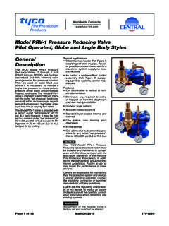
8 Outlet Pressure RangesTable 3. Maximum Inlet Pressures and TemperaturesTable 4. Minimum Differential Pressures for Safety Override SystemBoDy SIZES, NPS / DNEND CoNNECTIoN STyLESCast iron BodySteel and Stainless steel Body1 / 25 NPTNPT, SWE(1), CL150 RF, CL300 RF and PN 16/25/40 RF1-1/2 and 2 / 40 and 50 NPT, CL125 FF and CL250 RF3 and 4 / 80 and 100CL125 FF and CL250 RFCL150 RF, CL300 RF, PN 16 RF and PN 25/40 RF1. Available in steel bodies TyPEouTLET PRESSuRESPRING wIRE DIAmETERSPRING FREE LENGThPART NumBERCoLoR to 6 5 to 15 13 to to to to 1D7455T0012 1E395727192 Yellow Green BlackHigh-Pressure15 to 30 25 to 75 70 to to to to 1D7455T0012 1E395727192 Yellow Green BlackHigh Temperature15 to 100 80 to to to 14B9942X022 Unpainted UnpaintedBoDy mATERIALEND CoNNECTIoNmAXImum INLET PRESSuREmAXImum TEmPERATuREpsigbar F CCast (1)PN 16/25/40 RF (NPS 1, 1-1/2, 2 and 3 / DN 25, 40, 50 and 80) (1)PN 16 RF (NPS 4 / DN 100) 25/40 RF (NPS 4 / DN 100) (1)Stainless (1)PN 16/25/40 RF (NPS 1, 1-1/2, 2 and 3 / DN 25, 40, 50 and 80) (1)PN 16 RF (NPS 4 / DN 100) 25/40 RF (NPS 4 / DN 100) (1)1.
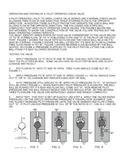
9 450 F / 232 C with standard seat ring, 600 F / 316 C with seal weld RANGESPRING CoLoRmINImum Pressure AT whICh moNIToRING PILoT CAN BE SETpsigbar6492HM10 to to psig / bar over normal downstream pressure25 to to psig / bar over normal downstream pressure70 to to psig / bar over normal downstream pressure6492 HTM15 to to psig / bar over normal downstream pressure80 to to psig / bar over normal downstream pressureBulletin :92B6 Figure 3. Type 92B Operational SchematicPrinciple of operationRefer to Figure 3. Compression of the pilot spring pushes diaphragm down and holds pilot Valve plug open. Outlet Pressure is changed by varying the amount of pilot spring steam enters the inlet of the Valve , it also enters the pilot supply line and flows through the open pilot Valve to the top of the main diaphragm.
10 The force created by this steam Pressure on the diaphragm overcomes the force of the main Valve spring opening the Valve plug and allowing steam to flow downstream. Downstream Pressure registers under the main diaphragm through the control line and tends to balance the diaphragm. Steam from the downstream system also registers under the pilot diaphragm through line. Pressure forces the diaphragm upward, permitting the pilot Valve plug to move toward the closed position. Flow of steam to the top of the main diaphragm is thereby reduced and the Pressure on main diaphragm drops due to the bleed through the orifice. The main Valve moves toward the closed position, allowing only enough steam flow to satisfy downstream steam demand increases, the downstream Pressure decreases below the setting of the pilot spring.