Transcription of Vickers Overhaul Manual Directional Controls - Eaton
1 control ValvesDG3V-8/DG5V-8 Hydraulic/Solenoid Pilot OperatedOverhaul ManualVickers Directional Controls2 ContentsSection I. Introduction3.. Model Code Breakdown4.. Section II. Description6.. Section III. Valve Operation7.. Section IV. Pilot Valve Section14.. Section V. Internal Valve Functions17.. Section VI. Installation18.. Section VII. Service, Inspection & Maintenance19.. Section VIII. Overhaul20.. DG5V-8-S/H-*(C)-1020.. DG3V-8-*(D) (2/8 / 28)-1021.. DG4V-3(S)-*A(L)/B(L)-FJ/FW-6021.. Section IX. Internal Body Passages & Plug Locations28.. Section X. Start-Up and Test31.. Eaton Hydraulics, Incorporated 2000 All Rights Reserved3 Section I.
2 - IntroductionA. Purpose of ManualThis Manual describes operational characteristics,maintenance requirements, and Overhaul information forVickers DG3V-8 and DG5V-8 series single stage and twostage pilot operated and hydraulic operated directionalvalves. The information contained herein pertains to thelatest design series as listed in Table Related PublicationsService parts and installation dimensions are not contained inthis Manual . The parts and installation drawings listed in Table1 are available from any Vickers sales engineering officeC. Model CodesVariations within each basic model series are covered in themodel code.
3 See Table 2. Each unit has a model codemarked on the main stage nameplate. Service inquiriesshould always include the complete model number as notedon the Descrip-tionApplication DrawingParts DrawingDG3V-8*ADG3V-8* *DDG5V-8*ADG5V-8* *C5007 04/EN/0496/SDG5V-8* *FDG5V-8*NTable 1. Related Publications4 Model CodeSpecial Seals(Omit if not required)F3 - Seals for fire resistant fluidsF6 - Seals for water glycolDirectional control ValveDG5V - Subplate mounting; solenoidcontrolled; pilot operated . Pressurerating 350 bar (5000 psi) for all Size8 - Valve size CETOP 8, NFPA D08 Pilot Valve TypeH - CETOP 3 High performanceS - CETOP 3 Standard performanceReducer Module(Omit if not required)WARNINGWhen the standard performancepilot is selected, the reducermodule is required to limit highdrain line pressure transients generatedduring PortsBlank.
4 4375-20 UNF-2B ThreadB -1/4 BSP ThreadSpool Types0 -Open to T all ports1 -Open P&A to T, closed B2 -Closed to T all ports3 -Closed P&B, open A to T4 -Tandem P to T, closed crossover6 -Closed P only, open A&B to T7 -Open P to A&B, closed T8 -Tandem P to T, open crossover9 -Open to T all ports over tapers11 - Open P&B to T, closed A31 - Closed P&A, open B to T33 - Closed P, open A&B to T over tapers52 - Closed center, regen. by sol. A 521 - Closed center, regen. by sol. B Spool control Modifications(Omit if not required)1 - Stroke adjustment (both ends) ( not available on D models)2 - Pilot choke adjustment (available on all models)3 - Pilot choke and stroke adjustments (both ends) (available on D models)7 - Stroke adjusters on A port end only ( not available on D models)8 - Stroke adjusters on B port end only (available on all models)27 - 2 and 7 combined (not available on D models)28 - 2 and 8 combined (available on al models)External Pilot PressureE -External pilot pressure.
5 Omit for internal pilot pressure Pilot DrainT - Internal pilot drain to T port. Omit for external pilot drain Valve in Pressure PortOmit if not - 0,3 bar (5 psi) checkQ - 2,5 bar (35 psi) checkR - 3,5 bar (50 psi) checkS - 5,0 bar (75 psi) check12345876 Spool/Spring ArrangementA - Spring offset to A portB - Spring centered with solenoid A removedC - Spring centeredD - Pressure centeredF -Spring offset to A port, shift to centerN - No spring detented (pilot valve only)Left Hand BuildL - Single solenoid models only, omit if not Override OptionsCETOP 3 piloted models only, omit if - Plain override in solenoid ends onlyH - Waterproof override in solenoid ends only H2- Waterproof override in both ends ofsingle solenoidP2- Plain override in both ends of singlesolenoidY- Lockable Manual override in solenoid ends only (DC models only)Z- No override in either endFast ResponseX - Not available for pilot pressures above 210 bar (3000 psi).
6 (Omit for standard internal pilot pressure models)910111213142347581101112131415961 55 Model Code (continued)201821172816 Solenoid Energization IdentityBlank - Standard arrangement for ( energize solenoid A tofollow flow P to A).V - Solenoid identification determinedby position of solenoid ( solenoid Aat port A end/solenoid B at port B end).Note4 and 8 type spools are always energization identity isindependent of mainstage Electrical Flag SymbolM - Features and options for pilot Valve Monitoring Switch(Omit if not required)S3- Limit switch normally open, wired toelectrical connector with AC w/PA5(H piloted models only)S4- Limit switch normally closed, wired to electrical connector with AC w//PA5(H piloted models only)S5- Limit switch - unwired(H piloted models only)S6- Position switch with DC w/U coils(H piloted models only)Coil TypeF - Flying lead (required for wiring housing option)
7 KU - Top exit flying leadP - Plug in SP1- Single spadeSP2- Dual spadeU - ISO 4400 (DIN 43650)X1 - Flameproof solenoids BASEEFA/CENELEC(S piloted models only)X2 - Explosion proof solenoids CSA/UL (S piloted models only)X3 - Explosion proof solenoids BASEEFA ExS (S piloted models only)Electrical Connections(F type coils only, omit if not required)PA - Insta plug, male receptacle onlyPB - Insta plug, male and female receptaclePA3-3 pin connectorPA5-5 pin connectorT - Wired terminal block (wiring housing option also required)Wiring HousingW- 1/2 NPT threaded connectionJ -20mm threaded connectionG - 1/2 BSPP threaded connectionElectrical Options(Omit if not required)U-type coils only1- Fitted connector2- Fitted connector and variable grommet6- Fitted connector with lightsSolenoid Indicator Lights(Omit if not required)Surge Suppressor/Damper(DC voltages only, omit if not required)D1- Encapsulated diode (industrial applications)D2- Encapsulated diode (mobile applications)D7- Encapsulated transzorbCoil Voltage Identification LetterPilot Valve Port Orifices(Omit if not required)
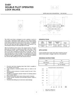
8 Design NumberSpecial Modifications(Omit if not required)2225262324271916171819262021222 3242527286 Section II. - DescriptionA. GeneralDirectional valves are devices used to change the flowdirection of fluid within a hydraulic circuit. A valve isdesigned to control the direction of movement of a workcylinder or the direction of rotation of a fluid Basic Four-Way Sliding Spool Directional ValveConstructionVickers valve bodies have a precision machined bore inwhich a very close tolerance spool is suspended on a film ofhydraulic fluid. Spool lands and body cavities are designedto divide the bore openings into separate chambers.
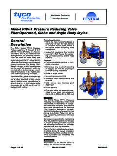
9 Ports inthe body lead into these chambers so that spool positiondetermines which ports are open or closed. See Figure 1. Oilflow is directed from one port to another within the body andout of a port to the workC. Two Stage Directional Valve ConstructionTwo stage Directional valves are pilot pressure operated . Atwo stage valve is constructed by combining a pilot valveand a larger main stage valve into one assembly. ADG4V-3(S) pilot valve is mounted on top of the main stagevalve. When a pilot valve solenoid is energized (activated),the pilot spool moves and fluid is diverted to the mainstage;thus controlling main stage spool movement.
10 Figure 2illustrates the basic construction of a two stage, pilotoperated Directional 1. Spool Type Four-Way ValveFigure 2. Typical DG5 Type Solenoid Controlled, Pilot operated Valve7 Section III. - Valve OperationA. GeneralDirectional valve operation is determined by four factors:spool type, spool positioning, method of control , and specialfeatures. Proper selection of the above factors establish andregulate desired flow paths through the internal ports of thevalve. The following information discusses those factors withrespect to valve Spool Types - Main Stage SectionOperation of spools are governed by their design as well asthe means of control .