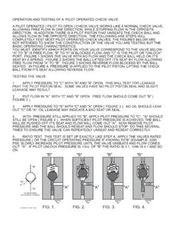
Transcription of Hydraulically pilot operated cartridge check valves Type ...
1 Hydraulically pilot operated cartridge check valves Type RHC and RHCE without and with hydraulic pre-reliefD 7165 check valves type RHC, RHCEA pril 2008-01 HAWE HYDRAULIK SESTREITFELDSTR. 25 81673 M 1978 by HAWE HydraulikPressure pmax= 700 barFlow Qmax= 200 devices are designed as seated valves and belong to the group of stop valves according to ISO 1219-1. Flow is blocked in the direction A B andpossible in the direction B closed passage, flow direction A B,can be opened (released) byhydraulic 'Blockage of zero-leakage cylinders when used together with leakage prone directional spool valves 'Return relief for directional valves during retraction of double acting cylinders'as a Hydraulically operated drain or circulation valveThe valve housings are designed as screw-in cartridges.
2 These valves are to be screwed into simply shaped tapped holes of a manifoldbody. The sealing of the consumer side A and B is via an O-ring and takes place at the contact area between the stepped valve bodyand the stepped shoulder of the core diameter at the location thread. Any standard steel drill (point angle 118 ) automatically forms thisstepped shoulder when the core diameter is drilled. Therefore reaming of the hole and bevels to help the seals slip in are not control side Z is generally sufficiently sealed to the consumer side B via an appropriate thread tolerances of valve screw andcore hole (see table with dimensions).There are versions with sealed thread and control piston available if this (minimum) leakage is version features a control piston relief where a an additional leakage port is apparent.
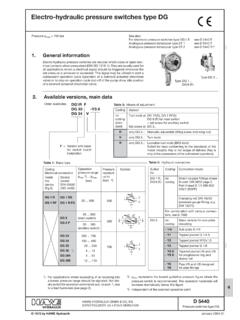
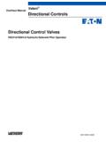
3 This enables opening without anydamping via the pressure apparent at port A (see examples in sect. 5).The following schematic illustrations show the design and a typical installation example where the mounting hole is blocked to theoutside with a tapped plug (conf. DIN 908 or 910) and seal ring (conf. DIN 7603).' valves without a pre-relief (type )The valve element is a ball. These valves allow full flow throughthe complete cross section A B oncethey are released. Therate of operation of the piston is moderated. Abrupt opening andpossible resultant relief shocks are substantially avoided. Ifshocks do occur during the trial run, however, an auxiliary restrictor must be provided in the control oil inlet, or a valve witha pre-relieving system must be used.
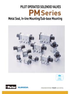
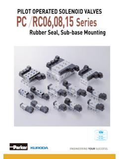
4 ' valves with a pre-relieving system (type )The valve component is a spherically ground piston (ball seat)with a built-in ball check valve which opens during valve relief prior to the main piston, thereby releasing a restrictor cross section for the shock-free relief, of the consumer capacities. Theyare used predominantly for high operating pressures and for largeconsumer capacities. An auxiliary restrictor in the control oil inletamplifies the efficacy of the pre-relieving feature.' valves with control piston relief (type )Available with/without pre-relief (see above).The opening pressure is rather independent from the return pressure (pB) with this version. This is possible because of the additional control piston relief via leakage port RHCType RHCEV ersionsAdditional sealing of the control pressure sideD 7165 page available, main RHCO rder example:RHC 4 VBasic typeOptionally with pre-reliefTrue pilotoperation ratio Size and versionNominal pilot operation ratio :1 Size and versionNominal pilot operation ratio :1 Nominal pilot operation ratio.
5 1 Standard versionWithout pre-relief1234561/02/13/24/35/4 With pre-relief----3V4V5V6V------4/3V5/4 VStandard versionWithout pre-relief123456 With pre-relief----3V4V5V6 VVersion with thread and control piston sealing(direct replacement for standard versions)Without pre-relief1121314151--11/021/131/241/351 /4 With pre-relief----31V41V51V--------41/3V51/4 VVersion with thread and control piston sealing(simple installation, non standard mounting hole)Without pre-relief131)23334353--13/023/133/243/3 53/4 With pre-relief----33V43V53V--------43/3V53/4 VVersion with thread and control piston sealing(simple installation, non standard mounting hole)Without pre-relief13 2333435363 With pre-relief----33V43V53V63 VFlow Qmax(lpm)1535551001502008153555100 Pressure pmax(bar) at port A, B, Z700700700500500500700700700500500 Main valve :1 Pre-relief----10:112:119 :1------26:121:1 Control volume (cm3) (weight) approx.
6 (g)204070140250500204070140250 True pilotoperation ratio Flow Qmax(lpm)153555100150200 Pressure pmax(bar) A, B, Z700700700500500500 LNon-pressurized to the tankMain :1 Pre-relief----10:112:119 :1 Control volume(cm3) (weight) approx. (g)2040701402505001) Type RHC 13 also available with thread ; Order coding: RHC 13 RHCE with control piston relief via additional leakage port at port Order example:RHCE 33 VBasic typeOptionally with pre-reliefD 7165 page dataTypeSpring-loaded seated ball valveMaterialAll steel design; housing part on the valve side hardened, valve seat groundMounting Screwed into location hole of a housing elementObserve the dimensional tolerance of the thread core diameter D1in sect. 4, as well asfootnote 1)Installation positionAnyConnectionsA, B= Main openingZ= Control oil connection L= Leakage oil connection, non-pressurized to the tankFlow directionB AFreeA BBlocked without zero leakage in neutral position (connection Z non-pressurized) if there is no pressure at B or a lower pressure than at A A BOpen, if the valve is pilot operated by a control pressure at Z (also see control pressure pSt)Opening pressure B Aapprox.
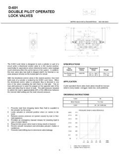
7 Bar; approx. 1 bar for RHC 1 pilotforBStASt+yD+ +y=Control pressure pst(bar)(Recommended valuecalculation) pilot -operation ratio see table Section 2pA= Pressure at A pB= Pressure at B |p see following characteristick= 1 for Type RHC= .. for Type RHCEP ressure fluidHydraulic oil conforming DIN 51524 part 1 to 3: ISO VG 10 to 68 conforming DIN limits: min. approx. 4, max. approx. 1500 mm2/s;opt. operation approx. 500 mm2 suitable for biological degradable pressure fluids types HEPG (Polyalkylenglycol) andHEES (Synth. Ester) at service temperatures up to approx. +70 : approx. -40 .. +80 CFluid: -25 .. +80 C, Note the viscosity range!Permissible temperature during start: -40 C (Note start-viscosity!), as long as the servicetemperature is at least 20K higher for the following degradable pressure fluids: Note manufacturer's specifications.
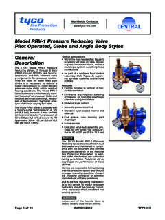
8 By considerationof the compatibility with seal material not over +70 resistance|p (bar)Flow resistance|p (bar)Flow Q (lpm)Flow Q (lpm)Oil viscosity duringthe measurementapprox. 60 mm2/s|p-Q curves D 7165 page 4SW = dimensions (V) 5(V),RHC 51(V)RHC 5/4(V),RHC 51/4(V) 4(V),RHC 41(V)RHC 4/3(V),RHC 41/3(V) 3(V),RHC 31(V)RHC 3/2,RHC 31 2,RHC 21 RHC 2/1,RHC 21 1,RHC 11 RHC 1/0,RHC 11/0O-ringa/fd2d1l3l2l1G4)Type Location holeThe mounting hole is blocked to the outside via a tappedplug (conf. DIN 908 or 910) and seal ring (conf. DIN 7603).1) D1determines the leakage of the control line with type RHC (V)Leakage lpm at 300 bar, when all tolerances are ) The thread depth T1-b and the distance of the hole #D3(connection side B) T1-c depend on the thread core hole depth fixed dimensions b, c, and a have to be maintained )Attention:Applies to type RHC 11.
9 51(V)All PTFE-swarf generated while screwing the valve in have to be thoroughly removed4) Thread G fine tolerance 4h/5H DIN 13 pages 21/225) This recess is only required with type RHC .1 to prevent damage of the seal ringMax. torque Mmax(Nm) RHC 1 .. 6(V), RHC 11 .. 51(V)RHC 1/0 .. 5/4V and RHC 11/0 .. 51/4(V)All dimensions are in mm, subject to change without notice!Seal ring oftype RHC (V) 3)O-ringNBR 90 ShTypeRHC 1(11)RHC 1/0(11/0)RHC 2(21)RHC 2/1(21/1)RHC 3(31) (V)RHC 3/2(31/2)RHC 4(41) (V)RHC 4/3(41/3) (V)RHC 5(51) (V)RHC 5/4(51/4) (V)RHC 6 (V)abcD11)D2D3D4D55)T1T2T35)15 3513 10 24 3817 15 29 4519 1624x29x224 15 10 36 5024 1830x36x230 18 12 42 5827 1836x42x242 28 12 50 7142 1942x49x2 Seal ring at thetapped plugonly withtype RHC 6(V)D 7165 page 5SW = a/fLocation holeThe mounting hole is blocked to the outside via a tappedplug (conf.
10 DIN 908 or 910) and seal ring (conf. DIN 7603). RHC 13 .. 53(V) and RHC 13/0 .. 53/4(V) 53(V)RHC 53/4(V) 43(V)RHC 43/3(V) 33(V)RHC 33 23 RHC 23 13 RHC 13/0 Max. torqueMmax(Nm)O-ring 2O-ring 1a/fl5l4l3l2l1G1)Type 53(V)RHC 53/4(V)36x42x212932282452134215223245451 8 RHC 43(V)RHC 43/3(V) 33(V)RHC 33 23 RHC 23 13 RHC 13/0 Seal ring at thetapped plugtT4T3+ maxD4D3D2D1H8L2L1 Type O-ring 1 NBR 90 ShoreO-ring 2AU 90 Shore(Type RHC NBR 90 Shore)Seal ringDetail "X"1) Core diameter = G 7165 page 6SW = RHCE 1 .. 6(V)Location holeThe mounting hole is blocked to the outside via a tapped plug (conf. DIN 908 or 910) and seal ring (conf. DIN 7603).TypeRHCE 1 RHCE 2 RHCE 3(V)RHCE 4(V)RHCE 5(V)RHCE 6(V)G1) torqueMmax(Nm)TypeRHCE 1 RHCE 2 RHCE 3(V)RHCE 4(V)RHCE 5(V)RHCE 6(V)L1* * * + + 90 Shore1) Thread GFine tolerance 4h/5H DIN 13, pages 21/22 Seal ringSeal ring at thetapped plugonly withtype RHC 6(V)D 7165 page 7SW = RHCE 13.