Example: stock market
PROGRAMMABLE AC & DC ELECTRONIC LOAD MODEL …
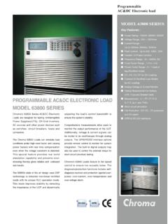
Programmable AC & DC Electronic load Chroma's 63800 Series AC&DC Electronic Loads are designed for testing Uninterruptible Power Supplies(UPS), Off-Grid Inverters, AC sources and
Tags:
Information
Domain:
Source:
Link to this page:
Documents from same domain
EASY˜USE SOFTWARE : THE 61600 SERIES SOFTPANEL
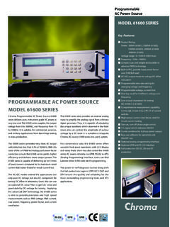
www.chromausa.comProgrammable AC Power Source Chroma Programmable AC Power Source 61600 series delivers pure, instrument grade AC power at very low cost. The 61600 series …
MODEL 63800 SERIES - Chroma Systems Solutions, …
www.chromausa.comModel 63800 Series All specifications are subject to change without notice. Please visit our website for the most up to date specifications. 1. LCD display 2. Function keypad :
Programmable AC Power Source
www.chromausa.comProgrammable AC Power Source Chroma AC power source 61500 series sets up the new standard for high performance AC power source. It …
MODEL 6500 SERIES - Chroma Systems Solutions, Inc.
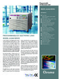
www.chromausa.comCOMPREHENSIVE WAVEFORM LIBRARY Up to 30 different distortion waveforms including line conditioner, line filter, triangle wave, pulse wave, and peak spike, etc. are stored in the waveform
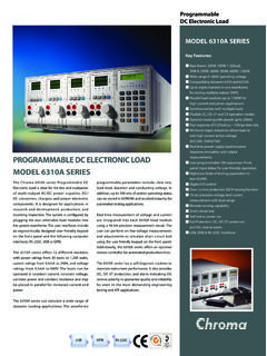
PROGRAMMABLE DC ELECTRONIC LOAD MODEL …
www.chromausa.comProgrammable DC Electronic Load Chroma's 63200 series of programmable electronic loads are designed for a wide variety of dc power conversion products including; DC …
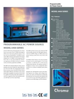
Key Features
www.chromausa.comThe 6400 Series AC Power Source supplies very clean output with typical output distortion less than 0.3% THD. The output is transformer …
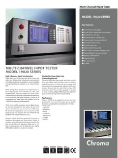
MULTI˜CHANNEL HIPOT TESTER MODEL 19020 …
www.chromausa.comSPECIFICATIONS 19020: Multi-Channel Hipot Tester 19020-4: Multi-Channel Hipot Tester (4CH) 19021: Multi-Channel Hipot Tester (AC) ORDERING INFORMATION Model 19020 19020-4 19021 19022 190 2-4 Mode AC/DC/IR AC/DC/IR AC DC/IR DC/IR Channel 10 4 10 10 4 Withstanding Voltage Test
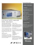
ELECTRICAL SAFETy ANALyZER MODEL …
www.chromausa.comMODEL 19032/19032-P Electrical Safety Analyzer Key Features : AC/DC/IR/GB/LC five instruments in one Function test up to 20A Programmable voltage output and limit
PROGRAMMABLE DC mELECTRONIC LOAD …
www.chromausa.comprogrammable parameters include: slew rate, load level, duration and conducting voltage. In addition, up to 100 sets of system operating status
Chroma Systems Solutions, Inc. Measuring Motor …
www.chromausa.comThe inductance or impedance of a motor can be a key parameter during the manufacture and servicing of both AC and DC motors. The inductance of both AC and DC motors can be measured using a low
Related documents

The RLC Circuit
www.math.ubc.caThe RLC Circuit The RLC circuit is the electrical circuit consisting of a resistor of resistance R, a coil of inductance L, a capacitor of capacitance C and a voltage source arranged in series.

Series RC, RL, and RLC Circuits Parallel RC, RL, and RLC ...
uhaweb.hartford.eduR, L, C Circuits Prof. Townsend Page 1 of 6 Series RC, RL, and RLC Circuits Parallel RC, RL, and RLC Circuits by Prof. Townsend MTH 352 Fall 2005
Chapter 8 Natural and Step Responses of RLC Circuits
www.ee.nthu.edu.tw1 Chapter 8 Natural and Step Responses of RLC Circuits 8.1-2 The Natural Response of a Parallel RLC Circuit. 8.3 The Step Response of a Parallel . RLC . Circuit
Chapter 13 The Laplace Transform in Circuit Analysis
www.ee.nthu.edu.tw1. Chapter 13 The Laplace Transform in Circuit Analysis. 13.1 Circuit Elements in the s Domain. 13.2-3 Circuit Analysis in the s Domain. 13.4-5 The Transfer Function and Natural Response
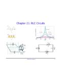
Chapter 21: RLC Circuits - University of Florida
www.phys.ufl.eduPHY2054: Chapter 21 2 Voltage and Current in RLC Circuits ÎAC emf source: “driving frequency” f ÎIf circuit contains only R + emf source, current is simple ÎIf L and/or C present, current is notin phase with emf ÎZ, φshown later sin()m iI t I mm Z ε =−=ωφ ε=εω m sin t …
MODEL 63800 SERIES - Chroma Systems Solutions, Inc.
www.chromausa.comModel 63800 Series All specifications are subject to change without notice. Please visit our website for the most up to date specifications. 1. LCD display 2. Function keypad : To select load mode, control mode, and system
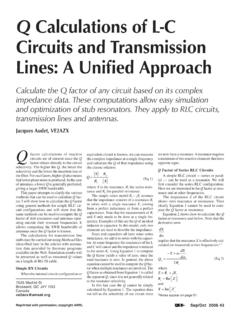
Q Calculations of L-C Circuits and Transmission Lines: A ...
www.ve2azx.net44 Sep/Oct 2006 R s and X and are the real and imaginary com- ponents of the RLC circuit impedance Z and ω= π2f. Equation 2 may be simplified as: r a s FL Q Rf C (Eq 3) where Qa is the Q factor below the resonant frequency Fr and f is the frequency at which Qa is …

AN11160 Designing RC snubbers - Nuts & Volts Magazine
www.nutsvolts.comDocument information AN11160 Designing RC snubbers Rev. 1 — 25 April 2012 Application note Info Content Keywords RC snubber, commutation, reverse recovery, leakage inductance, parasitic capacitance, RLC circuit and damping, MOSFET
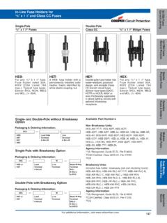
HEB- HET- HEY- HEX- - Electrical Sector – Eaton
www.cooperindustries.comWatertight Fuse Protection HEB in-line fuse holders are water resistant and easy to install. Protect fuses in locations exposed to water, weather, corrosive fumes, salt-spray, etc. Holders are two-