Transcription of Programming Guide VLT HVAC Drive FC 102 - Danfoss
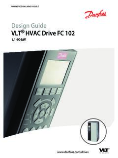
1 ENGINEERING TOMORROWP rogramming Guide VLT hvac Drive FC 102 Software version Frequency Safety92 How to Local Control How to Operate Graphical LCP (GLCP) How to Operate Numeric LCP (NLCP) Quick Transfer of Parameter Settings between Multiple Frequency Parameter Quick Menu Function Main Menu Parameter Changing Changing a Text Changing a Group of Numeric Data Value, Step by Read out and Programming of Indexed Initialization to Default Settings243 Parameter Parameter Parameters: 0-** Operation and Parameters: 1-** Load and Parameters: 2-** Main Menu - Parameters: 3-** Main Menu - Parameters: 4-** Main Menu - Parameters: 5-** Main Menu - Digital Parameters: 6-** Main Menu - Analog Parameters: 8-** Main Menu - Communications and Parameters: 9-** Main Menu - Parameters: 10-** Main Menu - CAN Parameters: 11-** Main Menu - Parameters: 13-** Main Menu - Smart Logic126 ContentsProgramming GuideM0010001 Danfoss A/S 10/2019 All rights Parameters: 14-** Main Menu - Special Parameters: 15-** Main Menu - Drive Parameters: 16-** Main Menu - Data Parameters: 18-** Main Menu - Data Readouts Parameters.
2 20-** Main Menu - FC Closed Parameters: 21-** Main Menu - Extended Closed Parameters: 22-** Application 22-2* No-Flow 22-3* No-flow Power 22-4* Sleep 22-5* End of 22-6* Broken Belt 22-7* Short Cycle 22-8* Flow Parameters: 23-** Time-based Parameters: 24-** Application Functions 24-0* Fire 24-1* Drive Parameters: 25-** Cascade Parameters: 26-** Analog I/O Option MCB Parameters: 30-** Special Parameters: 31-** Pressure Sensor/ Parameters 31-** Bypass 31-** Pressure Parameters: 32-** MCO Basic Parameters: 35-** MCB 114 Sensor Input Parameters: 36-** Programmable I/O Parameters: 40-** Special Parameters: 43-** Unit Readouts2724 Alarm Warning Extended Status Words2815 Parameter Parameter Default 0-** Operation and 1-** Load / Motor293 ContentsVLT hvac Drive FC 1022 Danfoss A/S 10/2019 All rights 2-** 3-** Reference / 4-** Limits / 5-** Digital In / 6-** Analog In / 8-** Communication and 9-** 10-** CAN 11-** 13-** Smart Logic 14-** Special 15-** Drive 16-** Data 18-** Info & R 20-** FC Closed 21-** Ext.
3 Closed 22-** Application 23-** Time Based 24-** Application Functions 26-** Analog I / O Option MCB 30-** Special 31-** Pressure Sensor/Bypass 32-** MCO Basic 35-** MCB 114 Sensor Input 36-** Programmable I/O 40-** Special 43-** Unit Readouts316 Index317 ContentsProgramming GuideM0010001 Danfoss A/S 10/2019 All rights hvac DriveFC 102 SeriesThis Guide can be used with allVLT hvac Drive frequencyconverters with software actual software versionnumber can be read fromparameter 15-43 Software Software VersionThis publication contains information proprietary toDanfoss.
4 By accepting and using this manual, the useragrees that the information contained in this is used solelyfor operating equipment from Danfoss , or equipment fromother vendors if such equipment is intended for communi-cation with Danfoss equipment over a serialcommunication link. This publication is protected underthe Copyright laws of Denmark and most other does not warrant that a software programproduced according to the guidelines provided in thismanual functions properly in every physical, hardware, orsoftware Danfoss has tested and reviewed the documen-tation within this manual, Danfoss makes no warranty orrepresentation, neither expressed nor implied, concerningthis documentation, including its quality, performance, orfitness for a particular no event shall Danfoss be liable for direct, indirect,special, incidental.
5 Or consequential damages arising out ofthe use, or the inability to use information contained inthis manual, even if advised of the possibility of suchdamages. In particular, Danfoss is not responsible for anycosts, including but not limited to those incurred as aresult of lost profits or revenue, loss or damage ofequipment, loss of computer programs, loss of data, thecosts to substitute these, or any claims by third reserves the right to revise this publication at anytime and to make changes to its contents without priornotice or any obligation to notify former or present usersof such revisions or following symbols are used in this a potentially hazardous situation which couldresult in death or serious a potentially hazardous situation which couldresult in minor or moderate injury.
6 It may also be usedto alert against unsafe important information, including situations thatmay result in damage to equipment or hvac Drive FC 1024 Danfoss A/S 10/2019 All rights AVM60 asynchronous vector modulationAAmpere/AMPACA lternating currentADAir dischargeAEOA utomatic energy optimizationAIAnalog inputAICA mpere interrupting currentAMAA utomatic motor adaptationAWGA merican wire gauge CDegrees CelsiusCBCircuit breakerCDConstant dischargeCDMC omplete Drive module: The Drive , feedingsection, and auxiliariesCEEuropean conformity (European safety standards)CMCommon modeCTConstant torqueDCDirect currentDIDigital inputDMDifferential modeDRCD isturbance rejection controlD-TYPED rive dependentEMCE lectromagnetic compatibilityEMFE lectromotive forceETRE lectronic thermal relay FDegrees FahrenheitfJOGM otor frequency when jog function is activatedfMMotor frequencyfMAXM aximum output frequency that the Drive applieson its outputfMINM inimum motor frequency from the drivefM,NNominal motor frequencyFCFrequency converter ( Drive )
7 FSPF ixed-speed pumpHIPERFACE HIPERFACE is a registered trademark byStegmannHOHigh overloadHpHorse powerHTLHTL encoder (10 30 V) pulses - High-voltagetransistor logicHzHertzIINVR ated inverter output currentILIMC urrent limitIM,NNominal motor currentIVLT,MAXM aximum output currentIVLT,NRated output current supplied by the driveIGBTI nsulated gate bipolar transistorkHzKilohertzLCPL ocal control panelLsbLeast significant bitmMetermAMilliampereMCMM ille circular milMCTM otion control toolmHInductance in milli HenrymmMillimetermsMillisecondMsbMost significant bit VLTE fficiency of the Drive defined as ratio betweenpower output and power inputnFCapacitance in nano FaradNLCPN umerical local control panelNmNewton meterNONormal overloadnsSynchronous motor speedOn/OfflineParametersChanges to online parameters are activatedimmediately after the data value is changedPbr.
8 Power of the brake resistor (average powerduring continuous braking)PCBP rinted circuit boardPCDP rocess dataPDSP ower Drive system: CDM and a motorPELVP rotective extra low voltagePmDrive nominal output power as high overloadPM,NNominal motor powerPM motorPermanent magnet motorProcess PIDP roportional integrated differential regulator thatmaintains the speed, pressure, temperature, etcRbr,nomNominal resistor value that ensures a brake poweron the motor shaft of 150/160% for 1 minuteRCDR esidual current deviceRegenRegenerative terminalsRminMinimum allowed brake resistor value by thedriveRMSRoot average squareRPMR evolutions per minuteRrecRecommended brake resistor resistance ofDanfoss brake resistorssSecondSCCRS hort-circuit current ratingSFAVMS tator flux-oriented asynchronous vectormodulationSTWS tatus wordSMPSS witch mode power supplySPCS mart process controllerTHDT otal harmonic distortionTLIMT orque limitTTLTTL encoder (5 V)
9 Pulses - transistor logicUM,NNominal motor voltageULUnderwriters Laboratories (US organization for thesafety certification)VVoltsVSPV ariable-speed pumpVTVariable torqueVVC+ voltage vector control plusTable Abbreviations and SymbolsIntroductionProgramming GuideM0010001 Danfoss A/S 10/2019 All rights VLT Native BACnet MCA 109, Programming Guideprovides information on how to configure andprogramme the system. VLT hvac Drive FC 102 Operating Guide providesinformation on mechanical and electrical instal-lation of the frequency converter . VLT hvac Drive FC 102 Design Guide holds alltechnical information about the frequencyconverter, customer design, and applications.
10 VLT hvac Drive FC 102 Programming Guideprovides information on how to programme andincludes complete parameter descriptions. MCT 10 Set-up Software Operating Guide enablesthe user to configure the frequency converterfrom a Windows -based PC publications and manuals are availablefrom Danfoss . See Danfoss for ConverterIVLT,MAXM aximum output ,NRated output current supplied by the frequency ,MAXM aximum output commandStart and stop the connected motor with LCP and are divided into 2 in group 1 have higher priority than functions ingroup 1 Reset, coast stop, reset and coast stop, quick stop,DC brake, stop, the [OFF] 2 Start, pulse start, reversing, start reversing, jog,freeze Function runningTorque generated on output shaft and speed from 0 RPMto maximum speed on frequency when t
